Enhanced ablation and mapping catheter and method for treating atrial fibrillation

Active Publication Date: 2005-01-20
BIOSENSE WEBSTER INC
View PDF29 Cites 65 Cited by
  • Summary
  • Abstract
  • Description
  • Claims
  • Application Information

AI Technical Summary

Benefits of technology

[0005] The invention is directed to an improved catheter and method for ablating linear lesions while ensuring delivery of cooling saline to the tissue being ablated. In one embodiment, the invention is directed to a catheter comprising an elongated generally-tubular catheter body having proximal and distal ends. An electrode assembly is provided at the distal end of the catheter body. The electrode assembly includes a porous electrode arrangement that is generally transverse to the catheter body. The porous electrode arrangement comprises one or more electrodes electrically connected to a suitable energy source and a porous sleeve mounted in surrounding relation to the one or more electrodes and defining an open space between the porous sleeve and the one more electrodes. One or more irrigation openings fluidly connect the open space to a lumen extending through the catheter through which fluid can pass. In use, fluid passes through the lumen in the catheter, through the one or more irrigation openings, into the open space and through the porous sleeve.
[0006] In another embodiment, the invention is directed to a catheter comprising an elongated generally-tubular catheter body having proximal an

Problems solved by technology

However, having an extendable electrode house in the catheter provides less degrees of freedom with respect to the shape, size and length of the tubular electrode.
Moreover, the physician has to deal with additional moving and manipulatable parts, adding complexity to the procedure.
Further, a retractable electrode can cause contamination because blood or coagulate on the electrode can be pulled

Method used


Image

  • Enhanced ablation and mapping catheter and method for treating atrial fibrillation
  • Enhanced ablation and mapping catheter and method for treating atrial fibrillation
  • Enhanced ablation and mapping catheter and method for treating atrial fibrillation

Examples


Embodiment Construction

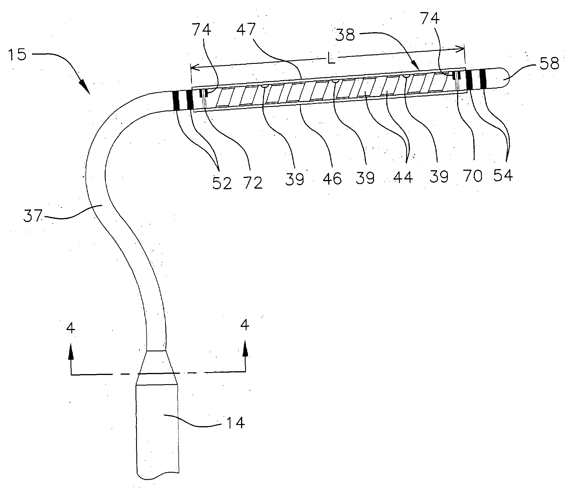
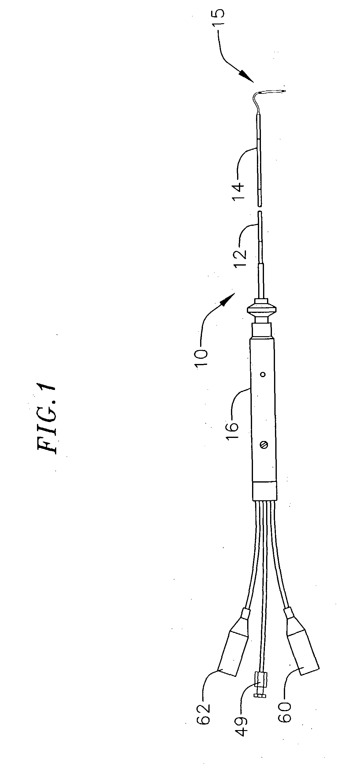
[0017] The invention provides a catheter having an irrigated tubular ablation electrode. As shown in FIG. 1, the catheter comprises an elongated catheter body 10 having proximal and distal ends with an electrode assembly 15 mounted at the distal end of the catheter body and a control handle 16 at the proximal end of the catheter body.

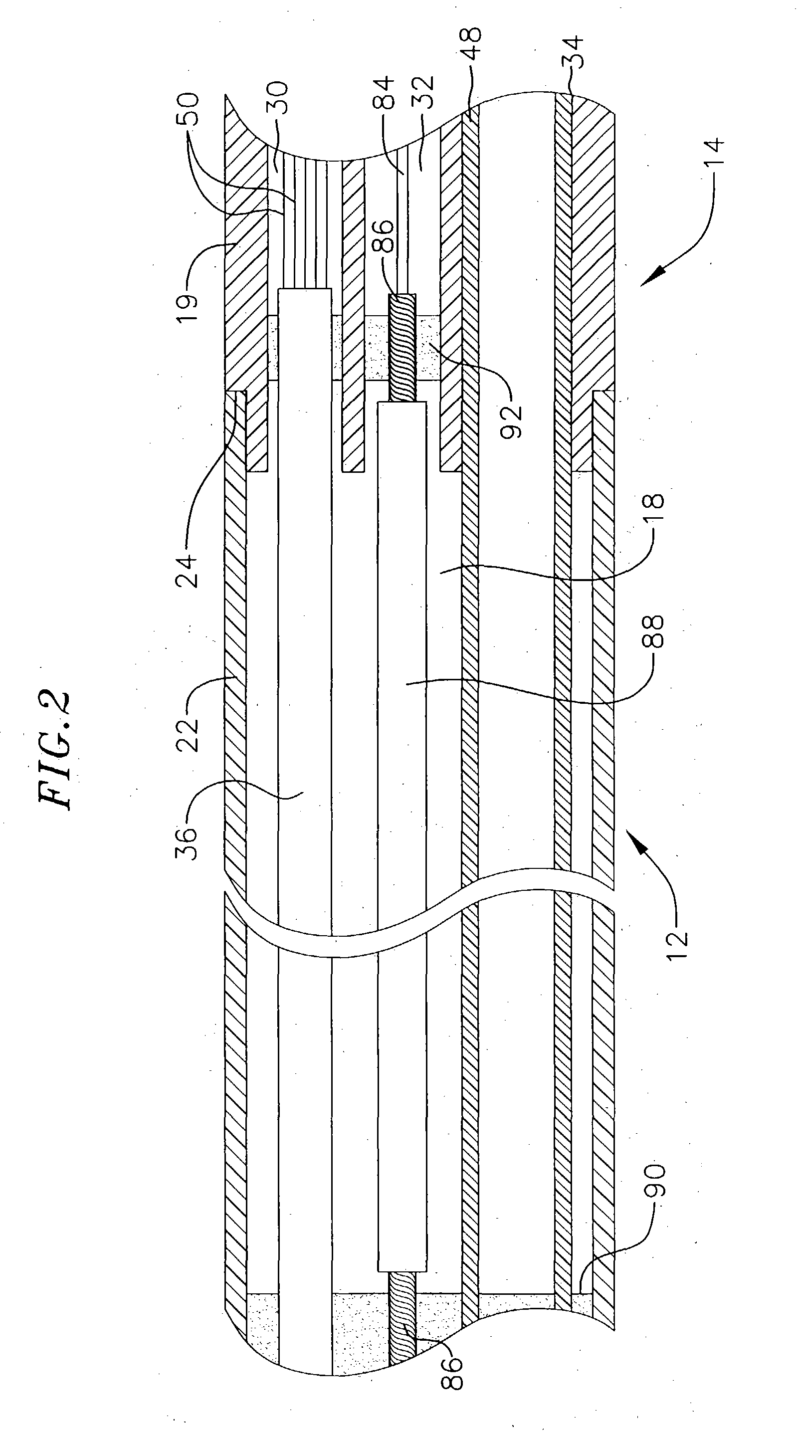
[0018] With reference to FIG. 2, the catheter body 10 comprises an elongated tubular construction having a relatively long proximal shaft 12 and a relatively short distal shaft 14. The proximal shaft 12 has a single, axial or central lumen 18. The proximal shaft 12 is flexible, i.e., bendable, but substantially non-compressible along its length. The proximal shaft 12 can be of any suitable construction and made of any suitable material. A presently preferred construction comprises an outer wall 22 made of polyurethane or PEBAX®. The outer wall 22 comprises an imbedded braided mesh of stainless steel or the like to increase torsional stiffness of the pr...


PUM

PropertyMeasurementUnit
Lengthaaaaaaaaaa
Fractionaaaaaaaaaa
Luminous fluxaaaaaaaaaa

Abstract

A catheter for ablating tissue is provided. The catheter comprises an elongated generally-tubular catheter body having proximal and distal ends. An electrode assembly is provided at the distal end of the catheter body. The electrode assembly including a porous electrode arrangement that is generally transverse to the catheter body. The porous electrode arrangement comprises one or more electrodes electrically connected to a suitable energy source and a porous sleeve mounted in surrounding relation to the one or more electrodes and defining an open space between the porous sleeve and the one more electrodes. One or more irrigation openings fluidly connect the open space to a lumen extending through the catheter through which fluid can pass. In use, fluid passes through the lumen in the catheter, through the one or more irrigation openings, into the open space and through the porous sleeve.

Description

FIELD OF THE INVENTION [0001] The present invention relates to an improved steerable electrode catheter having an irrigated ablation electrode that is particularly useful for treating atrial fibrillation. BACKGROUND OF THE INVENTION [0002] Atrial fibrillation is a common sustained cardiac arrhythmia and a major cause of stroke. This condition is perpetuated by reentrant wavelets propagating in an abnormal atrial-tissue substrate. Various approaches have been developed to interrupt wavelets, including surgical or catheter-mediated atriotomy. It is believed that to treat atrial fibrillation by radio-frequency ablation using a catheter, continuous linear lesions must be formed to segment the heart tissue. By segmenting the heart tissue, no electrical activity can be transmitted from one segment to another. Preferably, the segments are made too small to be able to sustain the fibrillatory process. A preferred technique for treating atrial fibrillation by radio-frequency ablation would b...

Claims


Application Information

Patent Timeline
IPC IPC(8): A61B5/042A61B17/00A61B18/14A61M25/00A61M25/16B29C33/38B29C33/52B29C35/08B29C41/10B29C41/14B29C67/00C08G73/10
CPCA61B5/0422A61B18/1492A61B2018/1472A61B2018/00065A61B2018/00839A61B2017/00243A61M25/1027A61M25/1029A61M25/1038A61B5/287B29C33/3842B29C33/52B29C35/08B29C41/10B29C41/14B29C2033/525B29C2035/0827B29L2031/7542C08G73/10A61B2018/00351A61B2018/00577A61B2018/00797A61B2018/1407A61B2218/002
Inventor O'SULLIVAN, MARTINLEE, JAMES K.HILL, IRMA
Owner BIOSENSE WEBSTER INC
Why Eureka
Try Eureka