Network apparatus and control method therefor

a network apparatus and control method technology, applied in the field of network apparatus and control methods therefor, can solve the problems of methods not being able to add a function later, occupying ports, and unable to add a dynamic servi

Inactive Publication Date: 2005-01-20
CANON KK
View PDF6 Cites 24 Cited by
  • Summary
  • Abstract
  • Description
  • Claims
  • Application Information

AI Technical Summary

Benefits of technology

The present invention has been made to overcome the conventional drawbacks, and has as its object to limit activation of an application program which a specific data processing apparatus is permitted to use or an application program depending on a specific data processing apparatus, and prevent unlimited use of an application or activation of an application which does not match the apparatus in a network apparatus detachable from a data processing apparatus.

Problems solved by technology

However, a low-end monochrome printing apparatus does not incorporate any network interface in the main body, and the network interface is generally supplied as a separate network card module.
However, when a large amount of data is transmitted during reception of print data, the port is occupied, and exchange of information management data stops.
However, all the above-mentioned methods only provide static functions incorporated in the network card module in advance.
These methods cannot add a function later, or add a dynamic service of changing a control method by an incorporated function.
The ROM capacity necessary to store these pieces of information increases, raising the cost.
Holding model-dependent application programs in the network card module poses problems in efficient use of the storage area in addition to an increase in ROM capacity.
Even if no malfunction occurs, the resource may be wasted.
It may be difficult to give the printer a resource later when the printing apparatus main body has already been commercially available.

Method used


Image

  • Network apparatus and control method therefor
  • Network apparatus and control method therefor
  • Network apparatus and control method therefor

Examples


first embodiment

<First Embodiment>

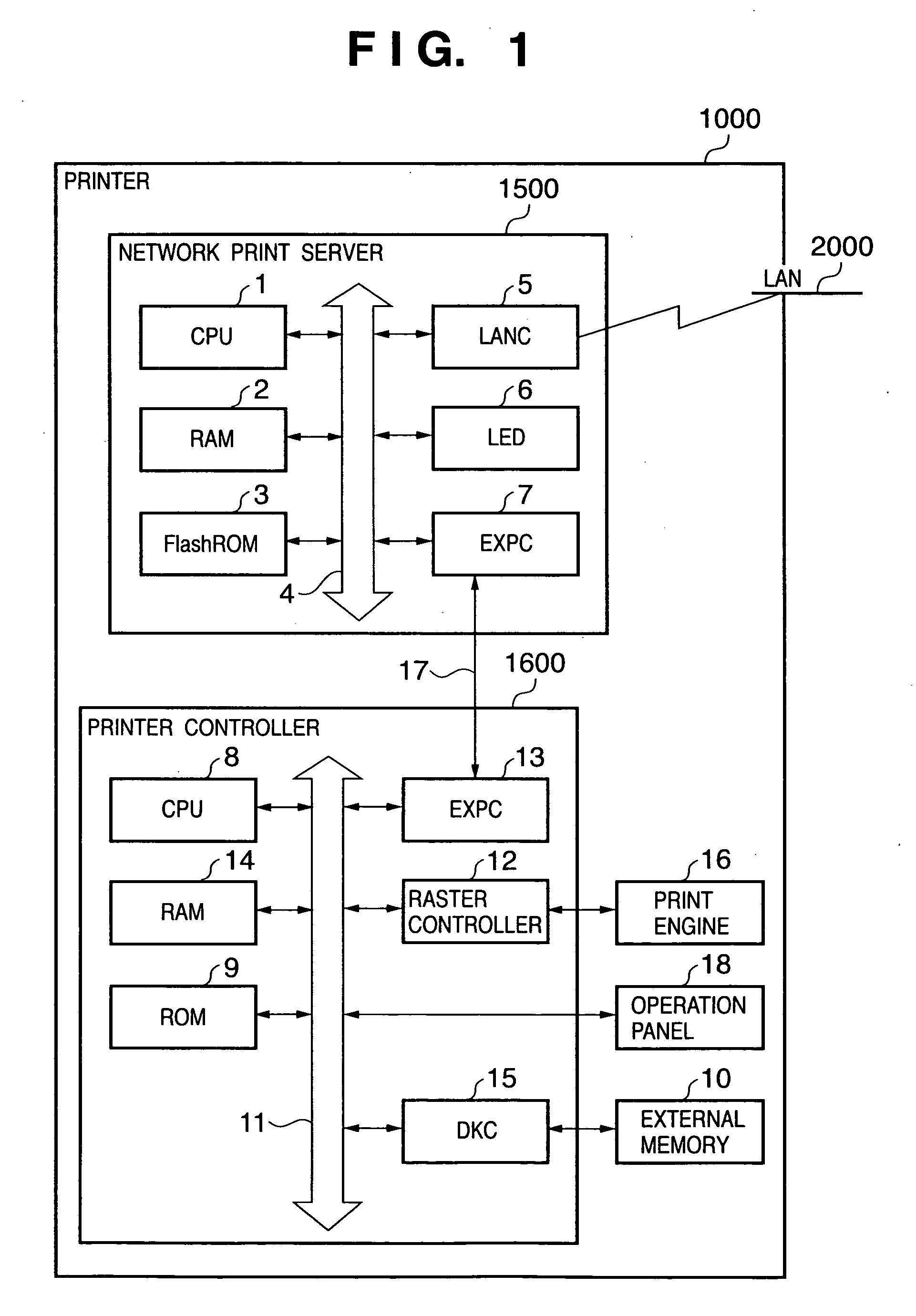
FIG. 1 is a block diagram for explaining the hardware configuration of a printing system according to the first embodiment. Reference numeral 1000 denotes a printer which is roughly formed from a network print server 1500 and printer controller 1600. The network print server 1500 and printer controller 1600 have independent control systems.

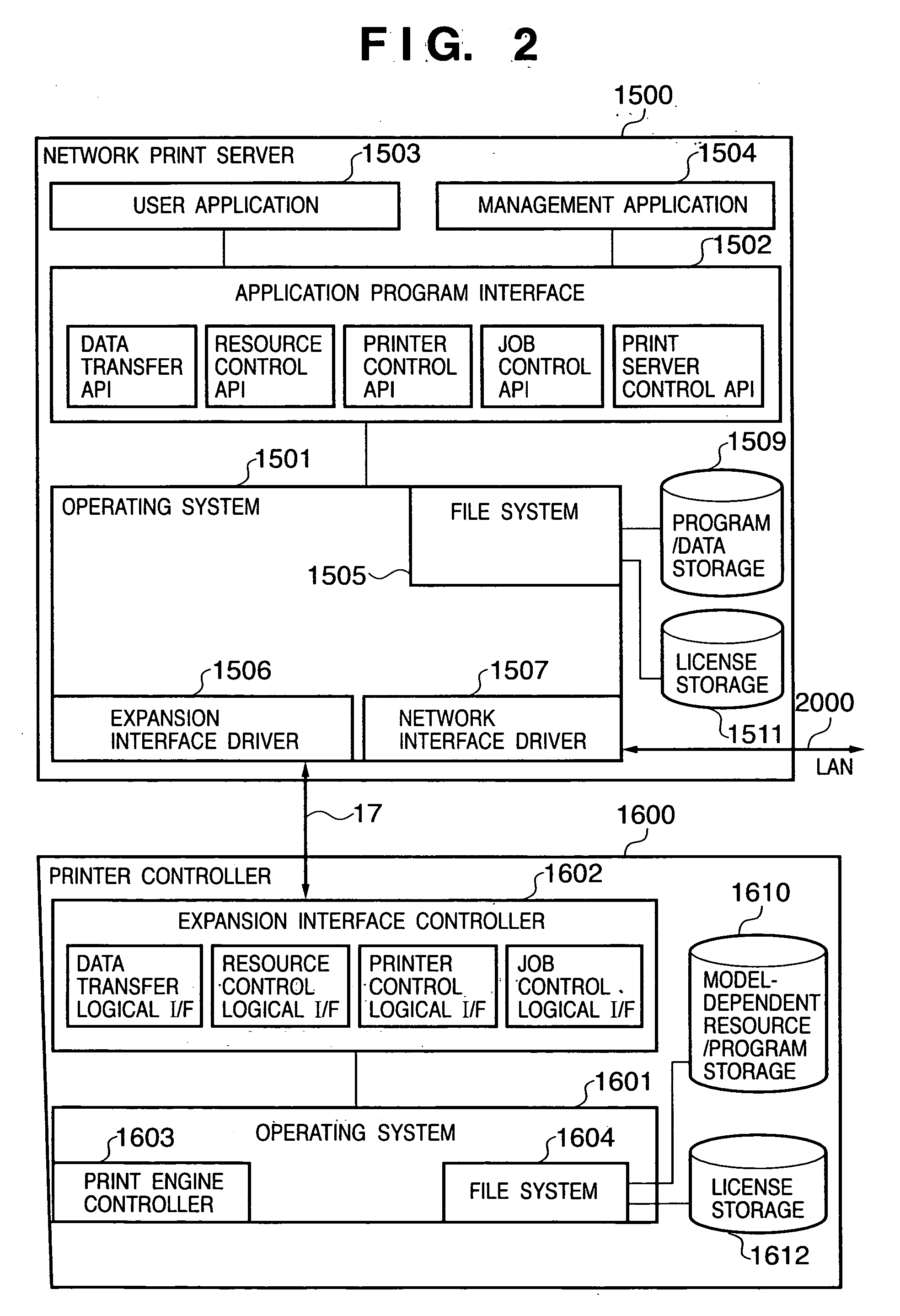
The network print server 1500 is a network apparatus which is implemented in the form of a network board module and is detachable from the printer 1000. In the network print server 1500, reference numeral 1 denotes a network print server CPU which executes various control operations on the basis of a control program stored in a rewritable Flash ROM 3. By using a predetermined network communication protocol, the CPU 1 communicates with an external device (not shown) such as a host computer connected to a local area network (LAN 2000) via a network controller (LANC 5) connected to a system bus 4. The CPU 1 comprehensively co...

second embodiment

<Second Embodiment>

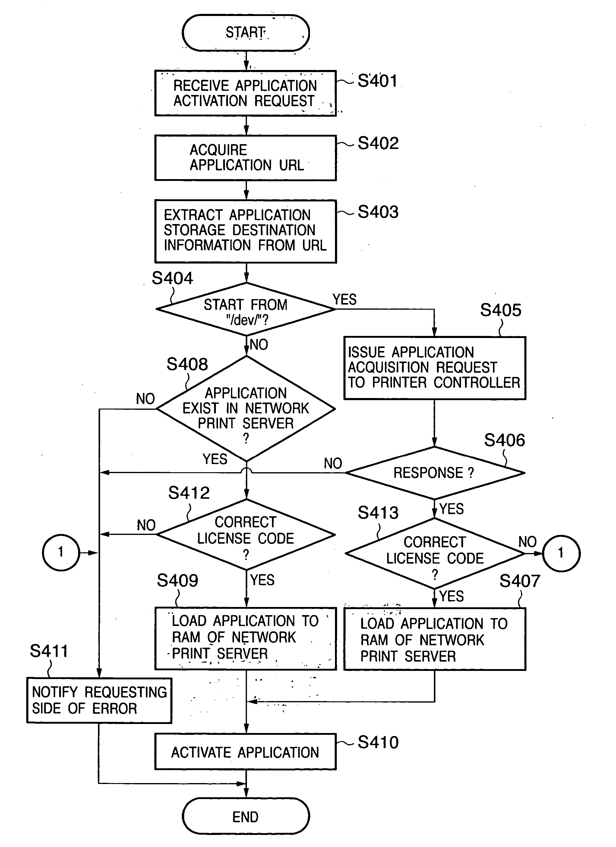
In the first embodiment, the storage destination of an application is determined from a URL included in an application activation request in accordance with the application activation request from an external device such as a host computer. In the second embodiment, an application designated as an automatic activation application upon activation of a printer 1000 is activated. Information for designating an automatic activation application is stored in advance in a predetermined storage area of a network print server 1500.

FIG. 5 is a flowchart showing an activation process method according to the second embodiment for an application program which runs in the network print server 1500. Steps S501 to S512 represent process steps, and control procedures corresponding to the steps are stored in a Flash ROM 3 of the network print server 1500. This process is also included in a management application 1504.

When the printer 1000 is powered on or reactivated by re...

third embodiment

<Third Embodiment>

The first and second embodiments have explained the application activation process. The third embodiment will describe an execution process for various commands during execution of an application. In the third embodiment, a plurality of types of command process functions can be distributed and held in a network print server and printer controller, thereby increasing the memory use efficiency.

FIG. 6 is a flowchart showing a process sequence for an instruction described in an application program which runs in a network print server 1500 according to the third embodiment. S601 to S610 represent process steps. Control procedures corresponding to the steps are stored in a Flash ROM 3 of the network print server 1500.

When an application program is activated in accordance with the flow shown in FIG. 4 or 5, one of instructions contained in a running application program is extracted and analyzed in step S601. If the instruction type is determined in step S602 to b...


PUM


Abstract

A network apparatus which is detachable from a data processing apparatus and is mounted in the data processing apparatus to connect the data processing apparatus and a network installs an application and stores authentication information corresponding to the application in the storage of the network apparatus. The network apparatus acquires authentication information corresponding to the application from the storage of the network apparatus and the data processing apparatus in accordance with an application activation request. The network apparatus determines, on the basis of the acquired authentication information, whether to permit activation of the application.

Description

CLAIM OF PRIORITY This application claims priorities from Japanese Patent Application Nos. 2003-197268 and 2003-197269 filed on Jul. 15, 2003 the entire contents of which are incorporated herein by reference. FIELD OF THE INVENTION The present invention relates to a network apparatus mountable in a data processing apparatus such as a printer, and a control method therefor. BACKGROUND OF THE INVENTION With recent spread of the Internet, it becomes popular to use a data processing apparatus such as a printing apparatus, copying machine, or facsimile apparatus while connecting it to a network. For example, as for a printing apparatus, high-end apparatuses such as a high-speed apparatus and color printing apparatus tend to incorporate a network interface. However, a low-end monochrome printing apparatus does not incorporate any network interface in the main body, and the network interface is generally supplied as a separate network card module. In this case, the printing apparatus m...

Claims


Application Information

Patent Timeline
Patent Type & Authority Applications(United States)
IPC IPC(8): H04L29/06
CPCH04L63/10
Inventor OKAZAWA, TAKASHITAKAHASHI, HIROHARU
Owner CANON KK
Why Eureka
Try Eureka