Retractable open end wrench

a wrench and open end technology, applied in the field of wrenches, can solve the problems of inconvenient use, problems in tapping and deburring holes, etc., and achieve the effect of reducing manufacturing costs and lead time, and easy manufacturing and deburring

Inactive Publication Date: 2005-01-27
APEX BRANDS
View PDF8 Cites 10 Cited by
  • Summary
  • Abstract
  • Description
  • Claims
  • Application Information

AI Technical Summary

Benefits of technology

[0008] It is a primary objective of this invention to provide a retractable open-end wrench allowing easy manufacturing and deburring to reduce the manufacturing costs and lead-time.

Problems solved by technology

Removing and repositioning the wrench causes inconvenience for the user and requires additional space to accommodate the operation for removing the wrench from the bolt or nut for recovering the wrench to an orientation facilitating further rotation under a state that the jaws disengage from the bolt or nut.
The above manufacturing process requires the use of several machining equipment and creates problems in tapping and deburring the hole, particularly for small-size wrenches.

Method used


Image

  • Retractable open end wrench
  • Retractable open end wrench
  • Retractable open end wrench

Examples


Embodiment Construction

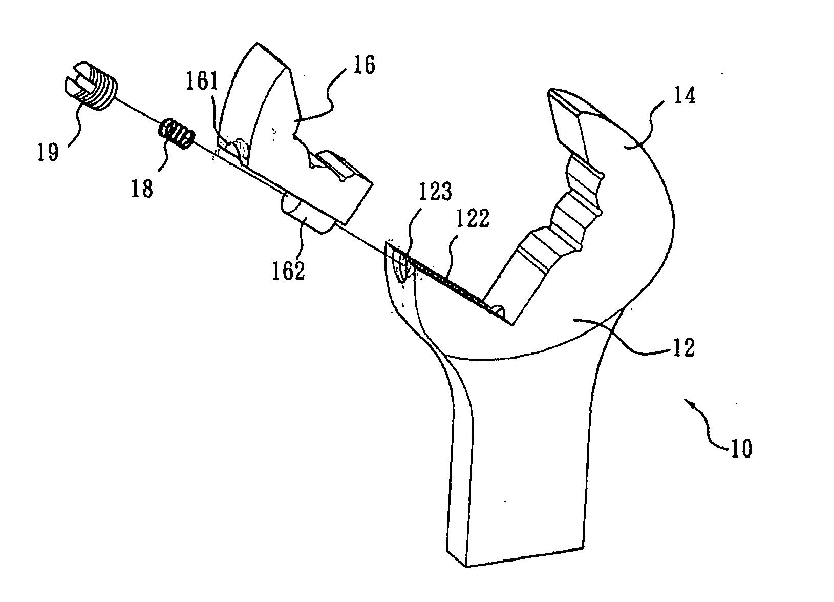
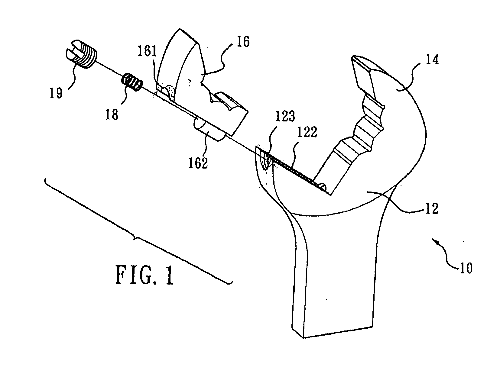
[0025]FIGS. 1 and 2 illustrate perspective views of a retractable open-end wrench 10 according to this invention. Wrench 10 comprises a web 12, a stationary jaw 14 projecting from a side of web 12, a movable jaw 16 provided at an opposite side of web 12 and forming an open end of a predetermined gap G with stationary jaw 14. Gap G preferably adapts to a width of a head of bolt or nut flats to which wrench 10 is designed to apply. For example, if the fastener has a hexagonal head, gap G is about the distance formed by two opposing, parallel flats of the head.

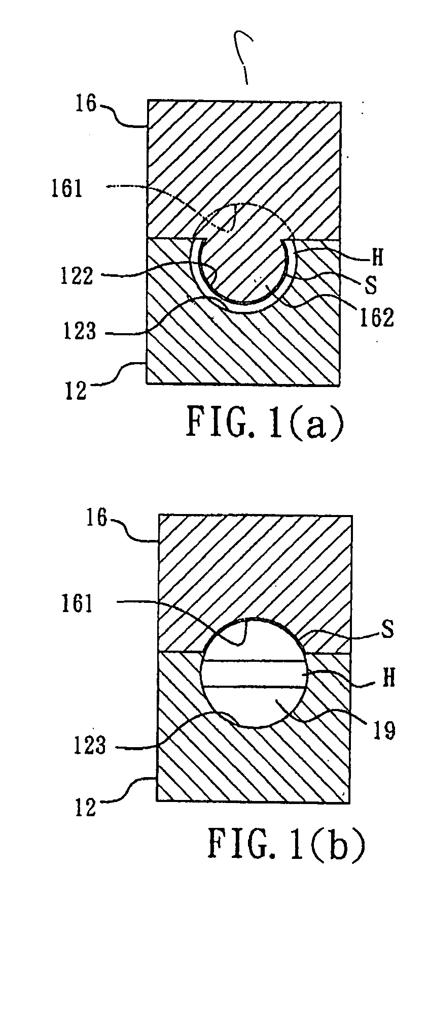
[0026] With reference to FIG. 1, web 12 is formed with a lower channel 122 at a location joining movable jaw 16 to allow for linear and resilient movement of movable jaw 16 with respect to web 12. Movable jaw 16 is formed with an upper channel 161 at location where jaw 16 joins with web 12. A post 162 projects from movable jaw 16 proximate upper channel 161.

[0027] With reference to FIG. 1(a), lower channel 122 has a major arc c...


PUM


Abstract

A retractable open-end wrench has a handle defining a web at one end thereof. A stationary jaw projects from a first side of the web, and a first channel is formed at a second side of the web opposite the first side, the first channel being defined by a first arc. A moveable jaw is received by the first channel and moves linearly through the first channel, wherein the jaws form an open end therebetween. A second channel formed in the movable jaw is defined by a second arc, wherein a length of the first arc is greater than a length of the second arc. Moreover, a first radius of the first arc is smaller than a second radius of the second arc, and the first channel and the second channel form a receiving hole.

Description

BACKGROUND OF THE INVENTION [0001] 1. Field of Invention [0002] This invention relates to a wrench, particularly to a retractable open-end wrench allowing itself to recover to an orientation to facilitate further rotation without repeatedly drawing up and fitting itself onto a bolt or nut. [0003] 2. Description of the Related Art [0004] Conventional wrenches for tightening or loosening bolts or nuts include locking and non-locking types in which the non-locking types allow for use with various sizes of bolts or nuts by adjusting an adjustment rack. [0005] Regardless of being a locking type or a non-locking type wrench, a user must remove the jaws of the wrench from the bolt after the bolt or nut is tightened or loosened upon rotating the wrench over a certain angle in a tightening or loosening direction, recovering the wrench to an orientation facilitating further rotation under a state that the jaws disengage from the bolt or nut, and then fitting the jaws onto the bolt or nut to p...

Claims


Application Information

Patent Timeline
Patent Type & Authority Applications(United States)
IPC IPC(8): B25B13/12B25B13/46
CPCB25B13/46B25B13/12
Inventor TUAN MU, HSIEN-CHUNG
Owner APEX BRANDS
Why Eureka
Try Eureka