Dual port intake device for an internal combustion engine formed by injection molding

a technology of injection molding and intake device, which is applied in the direction of air intake for fuel, combustion air/fuel air treatment, machines/engines, etc., can solve the problems of increasing the complexity reducing the efficiency of the intake device, and reducing the need for additional components.

Active Publication Date: 2005-01-27
HONDA MOTOR CO LTD +1
View PDF1 Cites 26 Cited by
  • Summary
  • Abstract
  • Description
  • Claims
  • Application Information

AI Technical Summary

Benefits of technology

[0015] The vacuum actuator may comprise a housing part which is integrally molded with a part of the intake manifold assembly such as the third block thereof so that this feature also may be integrally formed with the intake manifold assembly so as to eliminate a need for an additional component part. Such a vacuum actuator requires a solenoid valve for controlling the supply of negative pressure to the vacuum actuator, but the need for additional components can be minimized in this case also by integrally molding a stay member for supporting the solenoid valve with a part of the intake manifold assembly adjacent to the vacuum actuator.
[0016] The intake manifold assembly may further define a negative pressure chamber and a communication passage communicating the negative pressure chamber with the surge tank for minimizing the need for external or additional components. In such a case, a check valve may be fitted in the communication passage for storing negative pressure in the negative pressure chamber. Also, the support portion for rotatably supporting the selection valve may be provided in the intake manifold assembly, preferably between the first and third blocks thereof.

Problems solved by technology

However, the aforementioned proposal to form an intake manifold by injection molding plastic material is not suitable for molding an intake manifold having a more complex configuration as is the case when the intake manifold is to be used as a part of a dual port intake device because of the limited freedom in design.
In particular, the bearing arrangement for the selection valve for selectively closing one of the intake pipe sections tends to complicate the structure of the intake manifold.
The need for a negative pressure chamber and the piping for communicating the negative pressure source to the negative pressure chamber and vacuum actuator also adds to the complexity of the intake device.

Method used


Image

  • Dual port intake device for an internal combustion engine formed by injection molding
  • Dual port intake device for an internal combustion engine formed by injection molding
  • Dual port intake device for an internal combustion engine formed by injection molding

Examples


Embodiment Construction

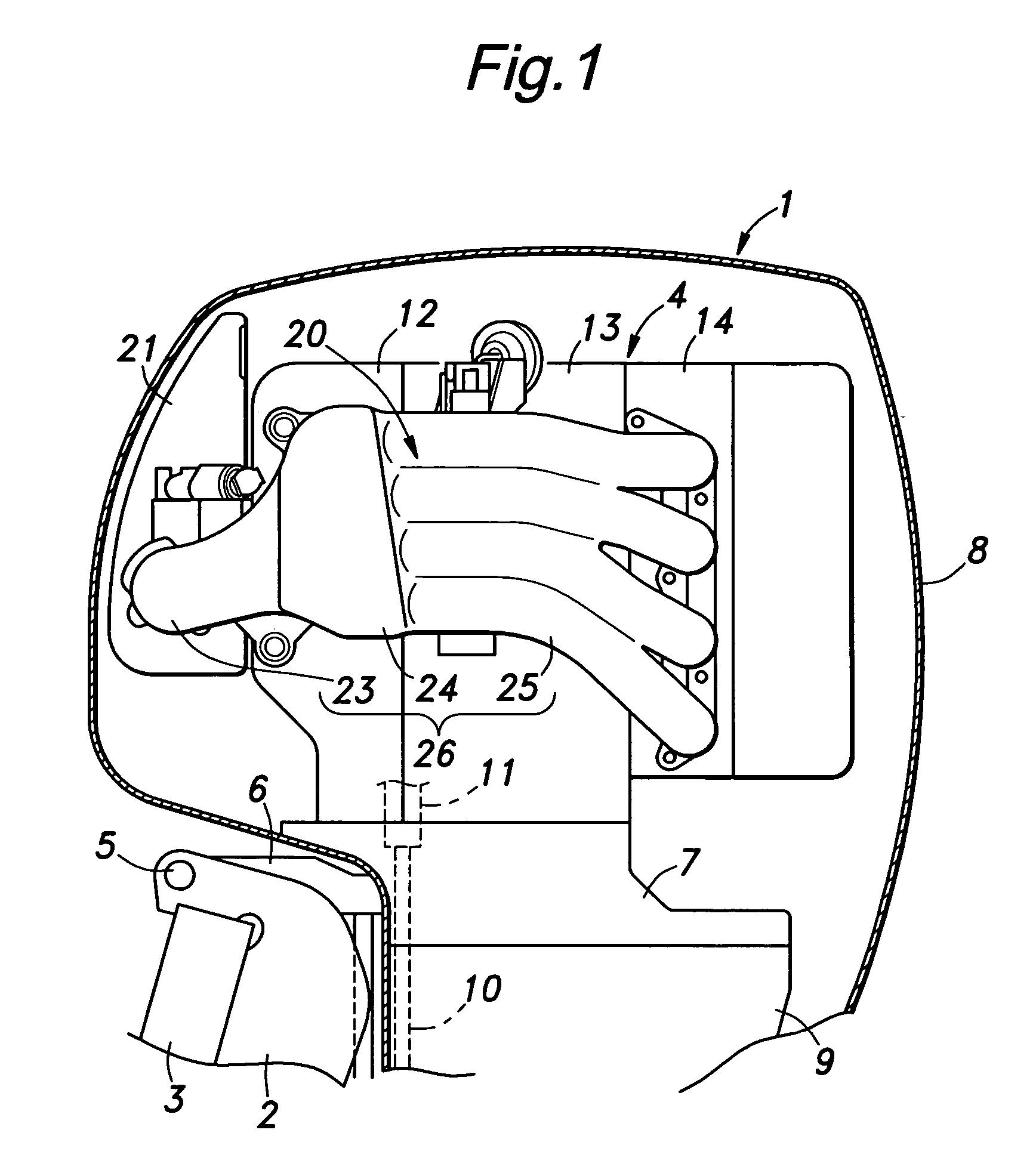
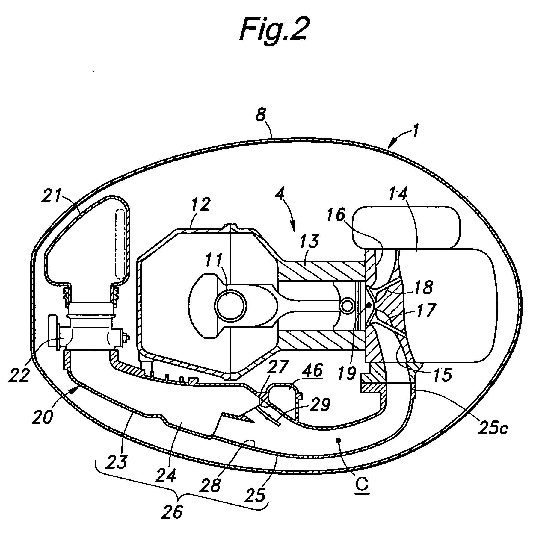
[0026]FIGS. 1 and 2 show an engine of an outboard motor. This outboard motor 1 is of a per se known type adapted to be attached to a stern board 3 via a stern bracket 2 except for the novel arrangement for the intake device. The engine 4 of this outboard motor 1 is mounted on a mount case 7, and the mount case 7 is substantially integrally provided with a swivel case 6 which is in turn connected to the stem bracket 2 so as to be freely vertically rotatable around a tilt shaft 5 extending horizontally. The engine 4 which is mounted on the mount case 7 is substantially entirely covered by a detachable engine cover 8.

[0027] The mount case 7 is connected to an upper end of an extension case 9, and a drive shaft 10 extending to a screw propeller (not shown in the drawings) is connected to a crankshaft 11 of the engine 4 in the mount case 7.

[0028] The engine 4 consists of an in-line four-cylinder vertical crankshaft engine, for instance, and comprises a crankcase 12, a cylinder block 13...


PUM

PropertyMeasurementUnit
pressureaaaaaaaaaa
lengthaaaaaaaaaa
weightaaaaaaaaaa

Abstract

In the dual port intake device of the present invention, the intake manifold assembly comprises three blocks each molded from a plastic material by injection molding, the three blocks consisting of a first block defining a half of the surge tank, a second block defining a half of the individual intake pipes and a third block defining a remaining half of the surge tank and a remaining half of the individual intake pipes. Thereby, the intake manifold assembly may be provided with various features for defining a pair of intake pipe sections arranged in a mutually parallel relationship while being made to be suitable for an injection molding process. Because the surge tank are defined by the first and third blocks (optionally with the aid of the second block) while the individual intake pipes are defined by the second and third blocks (optionally with the aid of the first block), the intake manifold assembly essentially consisting of three blocks can internally define essential features required for a dual port intake device without requiring additional component members.

Description

TECHNICAL FIELD [0001] The present invention relates to a dual port intake device for an internal combustion engine provided with a pair of intake pipe sections arranged in a mutually parallel relationship for each cylinder, and in particular to a dual port intake device for an internal combustion engine adapted to be formed by injection molding a plastic material. BACKGROUND OF THE INVENTION [0002] There have been a number of proposals to form an intake manifold by molding plastic material primarily for the purpose of minimizing the weight of the engine. For instance, Japanese patent laid open publication (kokai) No. 2001-342918 discloses an intake manifold consisting of two pieces that are bonded to each other along a plane in parallel with the direction of the intake flow to define individual intake pipes that are commonly connected to a surge tank. [0003] A number of dual port intake manifolds have also been proposed. According to the proposal disclosed in Japanese utility model...

Claims


Application Information

Patent Timeline
Patent Type & Authority Applications(United States)
IPC IPC(8): F02B27/02F02B31/08F02D21/08F02M25/07F02M35/04F02M35/10F02M35/104F02M35/108F02M35/16
CPCF02B27/0263Y02T10/146F02D9/1095F02D21/08F02M35/04F02M35/10039F02M35/10065F02M35/10216F02M35/10229F02M35/10288F02M35/10321F02M35/10347F02M35/1036F02M35/104F02M35/108F02M35/112F02M35/167F02B31/085F02B27/0215F02B27/0273Y02T10/12
Inventor IKUMA, TOMONORIKITO, KAZUYORI
Owner HONDA MOTOR CO LTD
Why Eureka
Try Eureka