Microvalve for controlling fluid flow

a micro-valve and fluid flow technology, applied in the direction of valve operating means/release devices, electrochemical generators, primary cell maintenance/servicing, etc., can solve the problems of reducing the efficiency of metal-air cells, cell failure prematurely, and undesirable power drain associated with prior-art micro-valves

Inactive Publication Date: 2005-01-27
DURACELL U S OPERATIONS
View PDF14 Cites 71 Cited by
  • Summary
  • Abstract
  • Description
  • Claims
  • Application Information

AI Technical Summary

Benefits of technology

[0016] In a first embodiment of the present invention, a microvalve for controlling fluid flow is disclosed as including: a body portion having a plurality of spaced openings formed therein; a shutter located adjacent to and substantially parallel with the body portion, the shutter having a plurality of spaced openings formed therein; a drive mechanism for causing the shu

Problems solved by technology

It has been determined, however, that the prior art microvalves have an undesirable amount of power drain associated therewith.
Free flow of ambient air through the metal-air cell, however, creates several problems that may lower the efficiency of a metal-air cell or even cause the cell to fail prematurely.
Thus, the capacity of the cell will continue to decrease unless air is excluded while the cell is not providing electrical energy to a load.
Another problem with allowing free flow of ambient air as the reactant is the difficulty in maintaining the proper humidity in the battery.
If the ambient humidity is greater than the equilibrium relative humidity value for the metal-air battery, the metal-air battery will absorb water from the air through the cathode and fail due to a co

Method used


Image

  • Microvalve for controlling fluid flow
  • Microvalve for controlling fluid flow
  • Microvalve for controlling fluid flow

Examples


Embodiment Construction

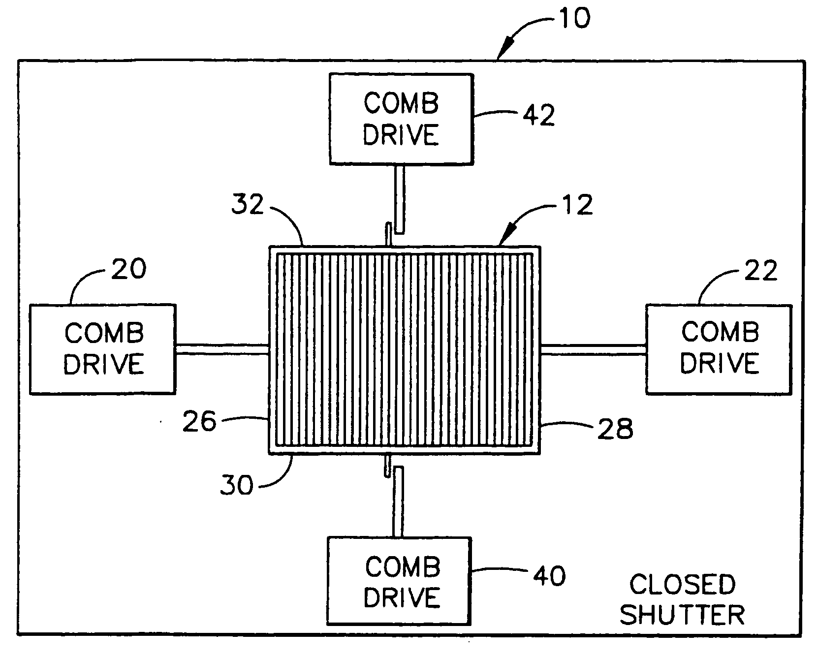
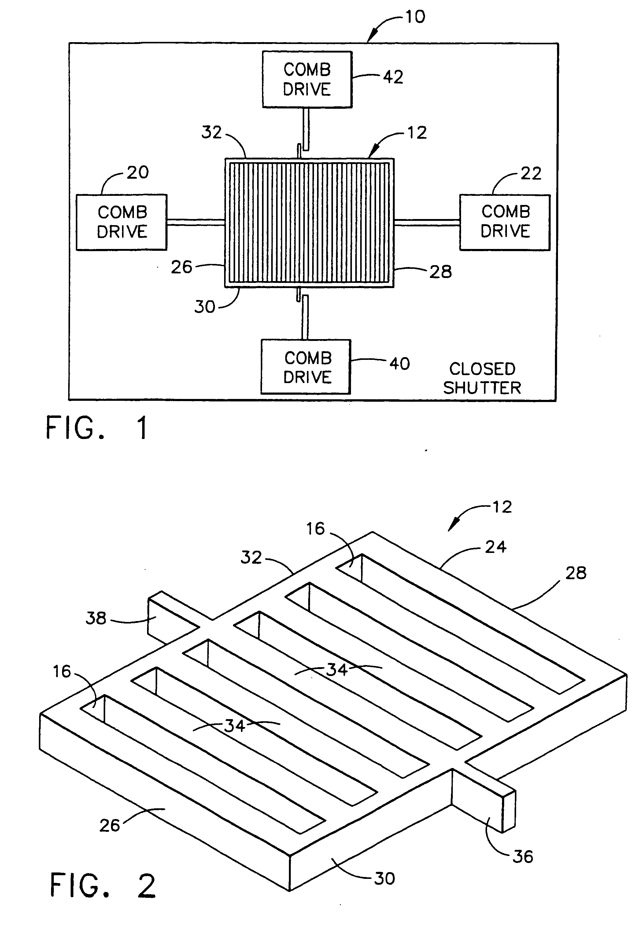
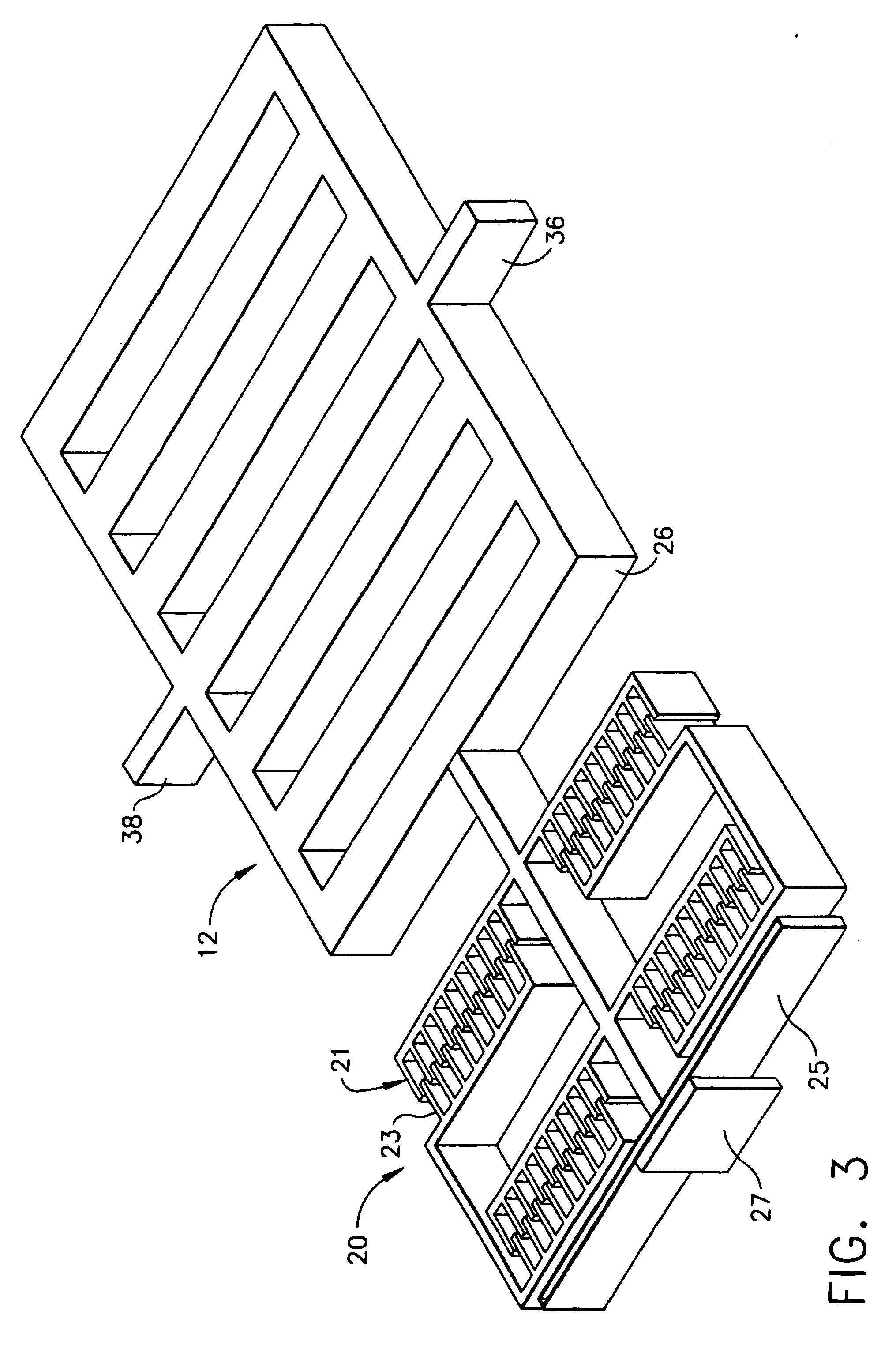
[0040] A preferred embodiment of the present invention involves an electrostatically-driven MEMS microvalve designed to control fluid flow. In this application, the term “electrostatically-driven” refers to a driving mechanism created from fixed charge due to an electrostatic potential between two surfaces. This differs from a “thermally-driven” microvalve in that the thermally-driven microvalve utilizes a resistive element that provides the heat energy necessary to drive the valve. Such a resistive element either provides a parasitic drain on the cell itself or requires an alternative power source to drive the valves. Magnetic or inductive systems, by contrast, use continuous current in a loop to generate an external magnetic field which in turn creates a magnetic force. An electrostatic valve, however, utilizes the charge of the cell to drive the valve so that the parasitic drain on the cell is much less than for thermal or magnetic valves.

[0041] In the preferred embodiments, the...


PUM


Abstract

A microvalve for controlling fluid flow, including a body portion having a plurality of spaced openings formed therein, a shutter located adjacent to and substantially parallel with the body portion having a plurality of spaced openings formed therein, a drive mechanism for causing the shutter to move laterally with respect to the body portion so that the spaced openings of the shutter are brought into and out of alignment with the spaced openings of the body portion, wherein the microvalve is in an open position and a closed position, respectively, and, a latching mechanism for preventing the shutter from moving laterally with respect to the body portion.

Description

CROSS-REFERENCE TO RELATED APPLICATION [0001] This application is a divisional of Ser. No. 10 / 048,082, filed Jan. 20, 2002, which claims priority to and is a 371 of PCT / US 00 / 19785 filed Jul. 20, 2000, which claims the benefit of 60 / 175,152, filed Jan. 7, 2000, and the benefit of 60 / 146,625, filed Jul. 30, 1999.FIELD OF THE INVENTION [0002] This invention relates to a microvalve for controlling fluid flow, and more particularly, to a latching system utilized with such microvalve. BACKGROUND OF THE INVENTION [0003] Microvalves employed to control the flow of fluid are presently in use, with several designs falling within a class known as micro electromechanical systems or “MEMS.” It will be appreciated that such microvalves are preferably driven thermally or electrostatically. In either case, slots or other types of openings are placed in an open or closed position, respectively, preferably within a shutter-type configuration so as to permit or prevent fluid from flowing therethrough...

Claims


Application Information

Patent Timeline
IPC IPC(8): F15C5/00F16K31/02F16K99/00H01M6/50H01M8/04H01M12/06H02N1/00
CPCF15C5/00Y02E60/50F16K99/0011F16K99/0013F16K99/0036F16K99/0046F16K99/0048F16K99/0051F16K2099/0071F16K2099/0074F16K2099/008F16K2099/0082H01M6/50H01M8/04089H01M12/06H02N1/008F16K99/0001Y10T137/86759
Inventor SHERMAN, FAIZ FEISALGARTSTEIN, VLADIMIRQUIRAM, DANIEL JONATHAN
Owner DURACELL U S OPERATIONS
Why Eureka
Try Eureka