Insert injection molding method and jig

Inactive Publication Date: 2005-01-27
CALSONIC KANSEI CORP
View PDF3 Cites 4 Cited by
  • Summary
  • Abstract
  • Description
  • Claims
  • Application Information

AI Technical Summary

Benefits of technology

[0023] By this insert injection molding method, the radiator core supp

Problems solved by technology

The above known conventional method, however, encounter such a problem that the gap between the insert and the core pin can not prevent from causing deformation of the insert, especially when the insert has a flat or plane portion, for the plane portion can be easily deformed by molten molding material injected

Method used


Image

  • Insert injection molding method and jig
  • Insert injection molding method and jig
  • Insert injection molding method and jig

Examples


Embodiment Construction

[0035] Throughout the following detailed description, similar reference characters and numbers refer to similar elements in all figures of the drawings.

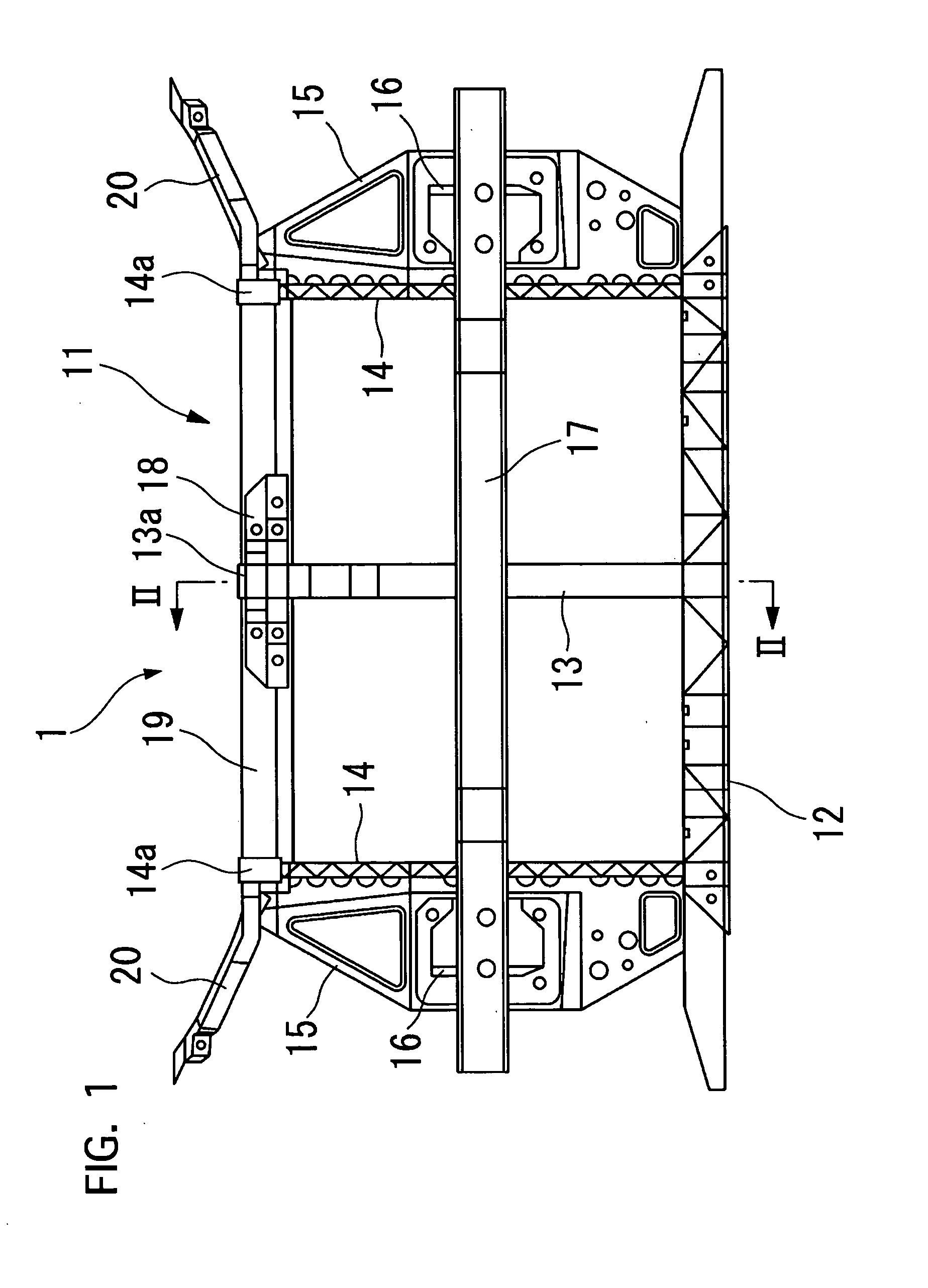
[0036] Referring to FIGS. 1 to 3 of the drawings, there is shown a radiator core support 1 of a motor vehicle, a molded part made by an insert injection molding method of a first preferred embodiment according to the present invention.

[0037] A radiator, not shown, is used for cooling coolant by air flow entering the radiator to get rid of excess engine heat, and resiliently supported by the radiator core support 1. The radiator core support 1 is mounted to the front end portion of a motor vehicle body.

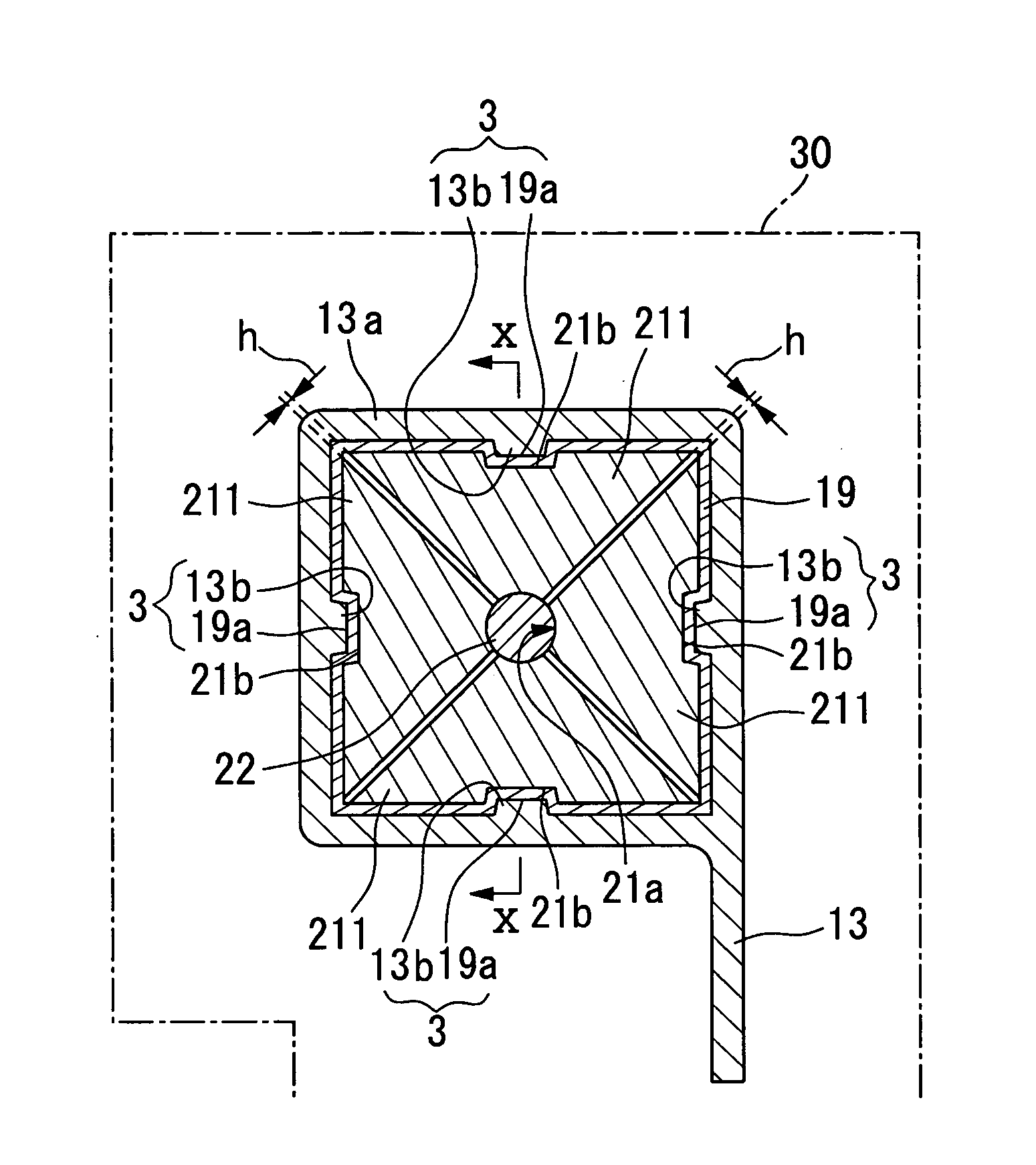
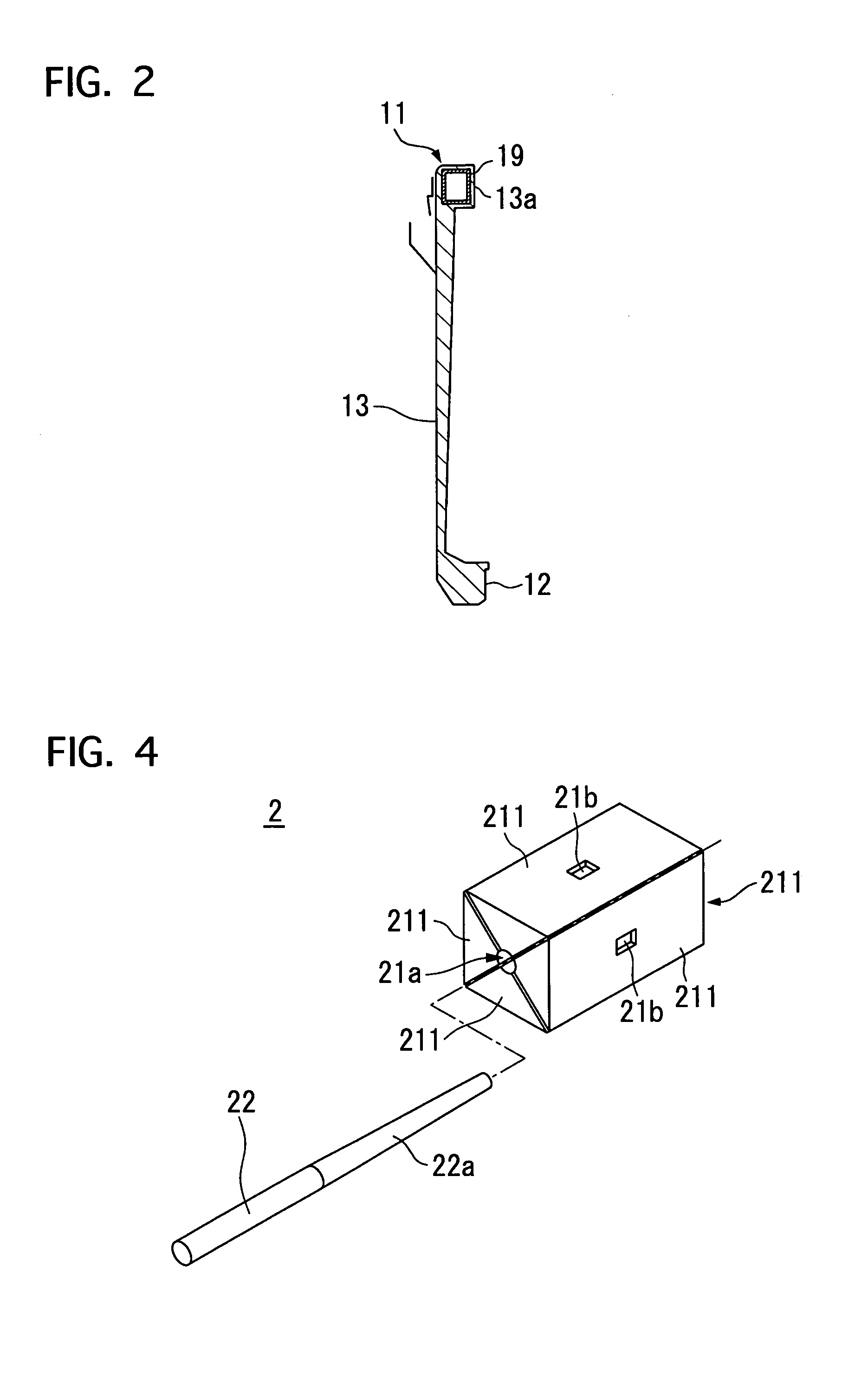
[0038] The radiator support 1 comprises upper radiator core support member 11 extending in a lateral direction of the vehicle body, a lower radiator core support member 12 extending in the lateral direction and located to be separated vertically from the upper radiator core support member 11, a hood lock stay 13 extending vertically ...


PUM

PropertyMeasurementUnit
Lengthaaaaaaaaaa
Pressureaaaaaaaaaa
Dimensionaaaaaaaaaa

Abstract

A radiator core support is made by an insert injection molding method. Four core members shaped in a triangular prism are built into a quadric-prism core and inserted into a rectangular tube, an upper radiator core support member. Then, an outwardly pressing member is inserted into a longitudinal slanted hole of the core to move and contact its members to the inner surfaces of the tube. The tube is located in a mold, into which molten molding material is injected. The tube is overmolded at the tops of a hood lock stay, and right and left side support members, being integrally formed out of rein. After cooling, drawing the pressing member from the core; then the core from the mold; and the molded part is removed from the mold.

Description

BACKGROUND OF THE INVENTION [0001] 1. Field of the Invention [0002] The present invention relates to an insert injection molding method in which an insert is located in a mold in advance of a molten molding material injection and then molded by molding material at its outer peripheral sides of the insert to obtain a molded part integrally formed with the insert and the molding material, and also relates to its jig used in the injection method. [0003] 2. Description of the Related Art [0004] An insert injection molding method of this kind is disclosed in Japanese patent laying-open publication (Tokkaihei) No. 11-277579. In this method, an insert, such as a pipe, is positioned in a mold in advance of a molten molding material injection, reinforced with a core pin arranged in a hole of the insert against pressure of the molding material during injection. The core pin is made smaller in diameter than the hole of the insert to have a gap between them for easy inserting and drawing-out. [...

Claims


Application Information

Patent Timeline
IPC IPC(8): B62D25/08B29C45/14B29C45/26B62D29/04
CPCB29L2031/3002B29C45/14836
Inventor MORI, TAKESHIKODAIRA, KENJITANIGUCHI, FUMIOOKAMURA, SHIGEKAZUFUJII, MASAHIRO
Owner CALSONIC KANSEI CORP
Why Eureka
Try Eureka