Micro gas generator including an initiator blast shield

a gas generator and initiator technology, applied in the direction of vehicular safety arrangements, pedestrian/occupant safety arrangements, transportation and packaging, etc., can solve the problems of affecting the performance of the associated device, many pretensioners once activated must be replaced, and the approach is quite time-consuming and expensive, so as to achieve gradual and controlled combustion of propellan

Inactive Publication Date: 2005-01-27
AUTOMOTIVE SYST LAB
View PDF15 Cites 14 Cited by
  • Summary
  • Abstract
  • Description
  • Claims
  • Application Information

AI Technical Summary

Benefits of technology

[0006] The above-referenced concerns are resolved by a gas generator that may tailor gas flow to function as a driving force, within a seatbelt pretensioner, for example. In accordance with the present invention, a micro gas generator contains a perforated housing, an annular bore seal, an initiator assembly housed within the bore seal and within the housing, and a propellant within the housing and ignitably communicating with the initiator assembly. An initiator blast shield at least partially covers the periphery of the initiator assembly insulating the same from the propellant bed. Insulation of the initiator assembly slows the rate of combustion of the propellant relative to the initial blast of the initiator. Stated another way, the initiator blast shield is used to arrest the initial blast of the initiator to result in a more gradual and controlled combustion of the propellant. As such, at least a portion of the total explosive output of the initiator is deflected to targeted areas of the propellant charge. In effect, the initiator blast shield produces a result similar to using a much lower charge mass initiator, without the associated engineering and development costs.

Problems solved by technology

In these designs, the explosive output of the initiator impacts the performance of the device associated therewith.
For example, many pretensioners once activated must be replaced due to the damage caused by initiator operation.
This approach, however is quite time-consuming and expensive.

Method used


Image

  • Micro gas generator including an initiator blast shield
  • Micro gas generator including an initiator blast shield
  • Micro gas generator including an initiator blast shield

Examples


Embodiment Construction

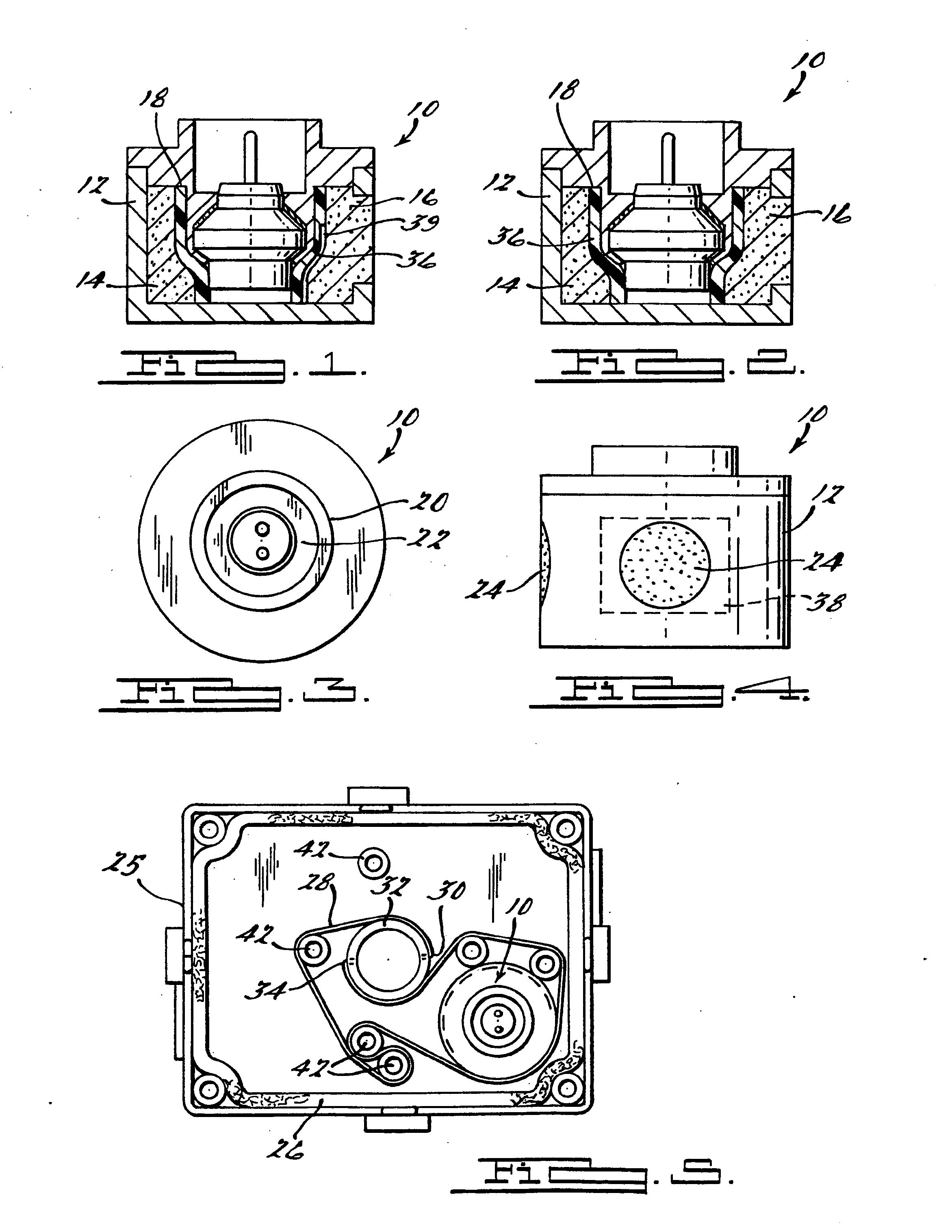
[0015] Referring to FIG. 1, there is shown a side sectional view of a micro gas generator in accordance with the present invention. A micro gas generator 10 is designed primarily for supplying and directing gas from the combustion of pyrotechnic materials into a seatbelt pretensioner for example, but is not limited thereto. Exemplary, but not limiting pretensioners and seat belt assemblies are described in co-owned U.S. Pat. Nos. 6,419,177, 6,460,794, 6,505,790, and 6,520,443, the teachings of which are herein incorporated by reference.

[0016] A housing 12 of gas generator 10 provides a body for containment of the other gas generator constituents, and forms a propellant chamber 14. A propellant or gas generant 16 is contained within chamber 14 and provides gas upon combustion thereof. A bore or chamber seal 18 is press fit, crimped, welded, or otherwise fixed within the generator 10 and about a first end 11 of the housing 12 to seal the chamber 14. An annular bore 20 is centrally or...


PUM


Abstract

A micro gas generator 10 is provided primarily for supplying and directing gas from the combustion of pyrotechnic materials into a seatbelt pretensioner 26, for example. A perforated housing 12 of gas generator 10 provides a body for containment of the other gas generant constituents, and forms a propellant chamber 14. A propellant or gas generant 16 is contained within chamber 14 and provides combustion thereof. An annular bore 20 is centrally oriented within the bore seal 18 thereby providing a seat for an associated initiator 22. An initiator blast shield 36 is encased about the initiator 22 thereby attenuating or mitigating the force and progression of the combustion of an ignition compound (not shown) within the initiator 22.

Description

CROSS-REFERENCE TO RELATED APPLICATIONS [0001] This application claims the benefit of U.S. Provisional Application Ser. No. 60 / 478,945 filed on Jun. 16, 2004.TECHNICAL FIELD [0002] The present invention relates generally to gas generator devices for restraint systems in automobiles, and relates more particularly to a seatbelt pretensioner incorporating a structure that simplifies tailoring of the associated gas generator output. BACKGROUND OF THE INVENTION [0003] As part of the overall vehicle occupant protection system, seatbelt assemblies have evolved considerably since their earliest inception. Improvements are continually sought relative to durability, ease of manufacturing, and general cost-effectiveness. [0004] One concern that continues to receive attention is the design of the seatbelt pretensioner. Seatbelt pretensioners generally function in concert with an associated retractor to tension and retract a seatbelt during a crash event. Typically, upon a crash event a pretensi...

Claims


Application Information

Patent Timeline
Patent Type & Authority Applications(United States)
IPC IPC(8): B60RB60R21/30B60R22/34B60R22/46F42B3/04
CPCB60R22/4628F42B3/04B60R2022/4647
Inventor STEVENS, BRUCE A.DUNHAM, STEVEN M.G.
Owner AUTOMOTIVE SYST LAB
Why Eureka
Try Eureka