Closing member control system
a control system and closing member technology, applied in the direction of motor/generator/converter stopper, dynamo-electric converter control, instruments, etc., can solve the disadvantageous variation in the tactile perception of the operator of the power window system, and achieve the effect of minimizing the variation in the tactile perception of the operator
- Summary
- Abstract
- Description
- Claims
- Application Information
AI Technical Summary
Benefits of technology
Problems solved by technology
Method used
Image
Examples
first embodiment
[0020] (First Embodiment)
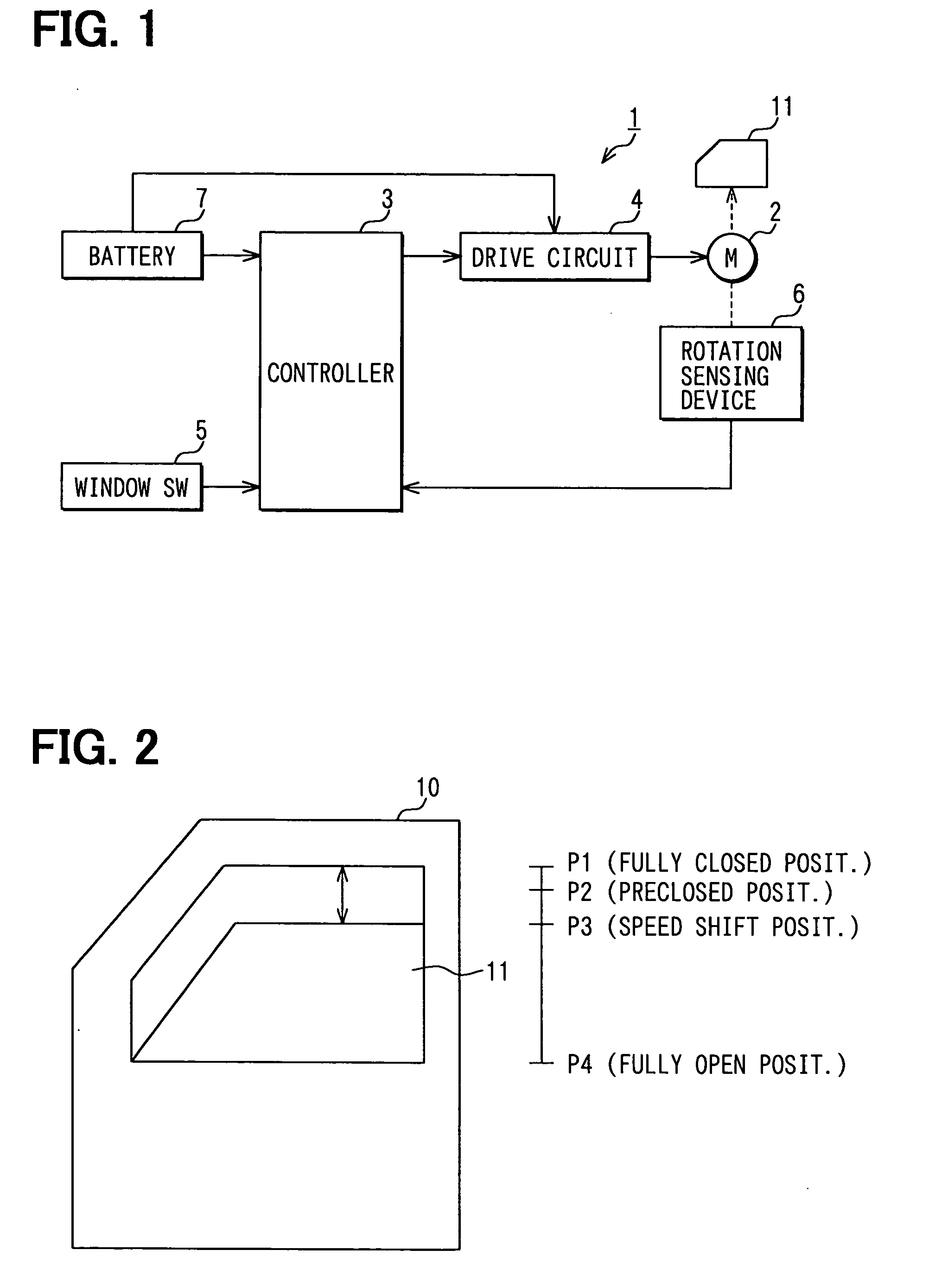
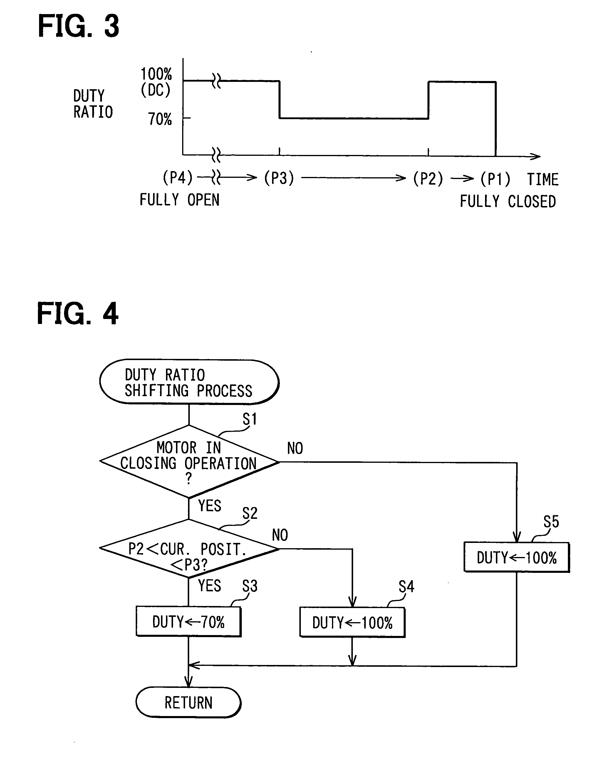
[0021] A first embodiment of the present invention will be described with reference to FIGS. 1 to 4.
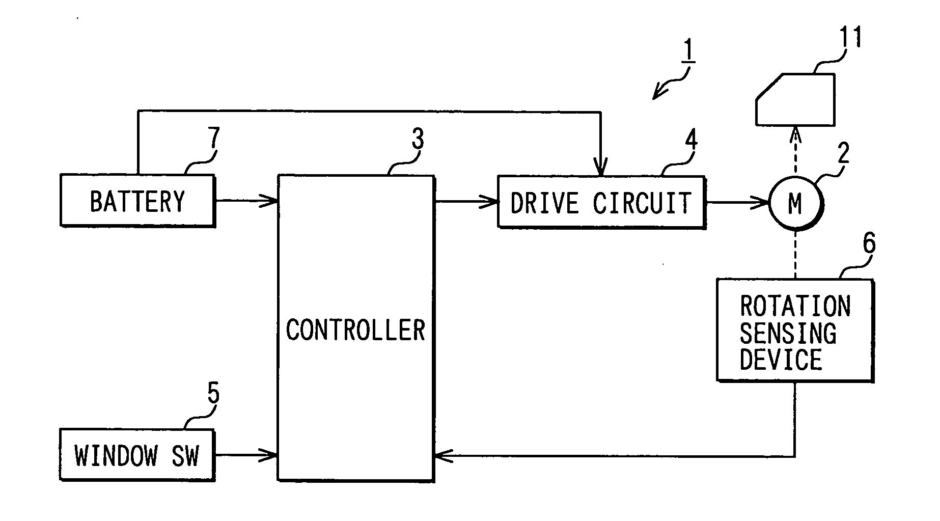
[0022] In a power window system (a closing member control system) 1 of FIG. 1, a window glass 11, which serves as a closing member, is arranged in a vehicle side door 10 of FIG. 2. The window glass 11 is raised or lowered, i.e., is closed or opened through rotation of a drive motor 2. The power window system 1 includes the drive motor 2, a controller 3, a drive circuit 4, a window switch (window SW) 5 and a rotation sensing device 6, each of which is arranged at a corresponding predetermined position in the vehicle. The controller 3 constitutes a pinching control means, a position sensing means and a motor output control means. The window switch 5 serves as a closing / opening operation commanding means. The rotation sensing device 6 also constitutes the position sensing means. Required electric power is supplied to the controller 3 from a vehicle battery 7. Al...
second embodiment
[0042] (Second Embodiment)
[0043] A second embodiment of the present invention will be described with reference to FIGS. 5 and 6. In the second embodiment, the duty ratio shifting process of the controller 3 slightly differs from that of the first embodiment. Thus, the following description will be mainly focused on the duty ratio shifting process of the controller 3.
[0044] The controller 3 supplies the electric power to the drive motor 2 at the duty ratio (Duty) of 100% to operate the drive motor 2 at the normal speed throughout the entire operational interval (i.e., a P1 to P4 interval) in the opening operation of the window glass 11. Furthermore, with reference to FIG. 5, the controller 3 supplies the electric power to the drive motor 2 at the duty ratio (Duty) of 100% to operate the drive motor 2 at the normal speed in the interval from the fully open position P4 to the speed shift position P3 (the P4 to p3 interval). Also, the controller 3 supplies the electric power to the dri...
third embodiment
[0060] (Third Embodiment)
[0061] A third embodiment of the present invention will be described with reference to FIGS. 7 and 8. In the third embodiment, the duty ratio shifting process of the controller 3 slightly differs from that of the first embodiment. Thus, the following description will be mainly focused on the duty ratio shifting process of the controller 3.
[0062] The controller 3 of the third embodiment supplies the electric power to the drive motor 2 at the duty ratio (Duty) of 100% throughout the entire operational interval (i.e., a P1 to P4 interval) in the opening operation of the window glass 11.
[0063] Furthermore, with reference to FIG. 7, the controller 3 supplies the electric power to the drive motor 2 at the duty ratio (Duty) of 100% to operate the drive motor 2 at the normal speed in the interval from the fully open position P4 to the speed shift position P3 (the P4 to P3 interval) and also in the interval from the preclosed position P2 to the fully closed positio...
PUM
 Abstract
Description
Claims
Application Information
 - R&D
- Intellectual Property
- Life Sciences
- Materials
- Tech Scout
- Unparalleled Data Quality
- Higher Quality Content
- 60% Fewer Hallucinations
Browse by: Latest US Patents, China's latest patents, Technical Efficacy Thesaurus, Application Domain, Technology Topic, Popular Technical Reports.
© 2025 PatSnap. All rights reserved.Legal|Privacy policy|Modern Slavery Act Transparency Statement|Sitemap|About US| Contact US: help@patsnap.com


