Closing member control system

a control system and closing member technology, applied in the direction of motor/generator/converter stopper, dynamo-electric converter control, instruments, etc., can solve the disadvantageous variation in the tactile perception of the operator of the power window system, and achieve the effect of minimizing the variation in the tactile perception of the operator

Active Publication Date: 2008-04-22
DENSO CORP
View PDF33 Cites 26 Cited by
  • Summary
  • Abstract
  • Description
  • Claims
  • Application Information

AI Technical Summary

Benefits of technology

[0007]The present invention addresses the above disadvantage. Thus, it is an objective of the present invention to provide a closing member control system, which can minimize a variation in the tactile perception of an operator of the closing member control system from product to product.
[0008]To achieve the objective of the present invention, there is provided a closing member control system, which includes a drive motor, a pinching control means, a position sensing means and a motor output control means. The drive motor drives a closing member between a fully open position and a fully closed position. The pinching control means is for monitoring pinching of an object by the closing member in a closing operation of the closing member toward the fully closed position and is also for controlling the drive motor in a manner that enables release of the object from the closing member upon occurrence of the pinching of the object by the closing member. The pinching control means determines that the object is pinched by the closing member when the drive motor is decelerated in the closing operation of the closing member, and thereby a change in a rotational speed of the drive motor per unit time decreases below a threshold value in the closing operation. The position sensing means is for sensing a current position of the closing member. The motor output control means is for controlling an output of the drive motor. The motor output control means reduces the output of the drive motor when the closing member reaches a first intermediate position, which is between the fully open position and the fully closed position, in the closing operation of the closing member. The motor output control means increases the output of the drive motor based on a position signal, which is received from the position sensing means and which indicates that the position of the closing member in the closing operation is in a second intermediate position located on a fully closed position side of the first intermediate position. The second intermediate position is located in a pinch-monitoring disabled zone, in which the monitoring of the pinching of the object through the pinching control means is disabled.

Problems solved by technology

Thus, tactile perception of an operator of the power window system disadvantageously varies from product to product.

Method used


Image

  • Closing member control system
  • Closing member control system
  • Closing member control system

Examples


first embodiment

[0022]A first embodiment of the present invention will be described with reference to FIGS. 1 to 4.

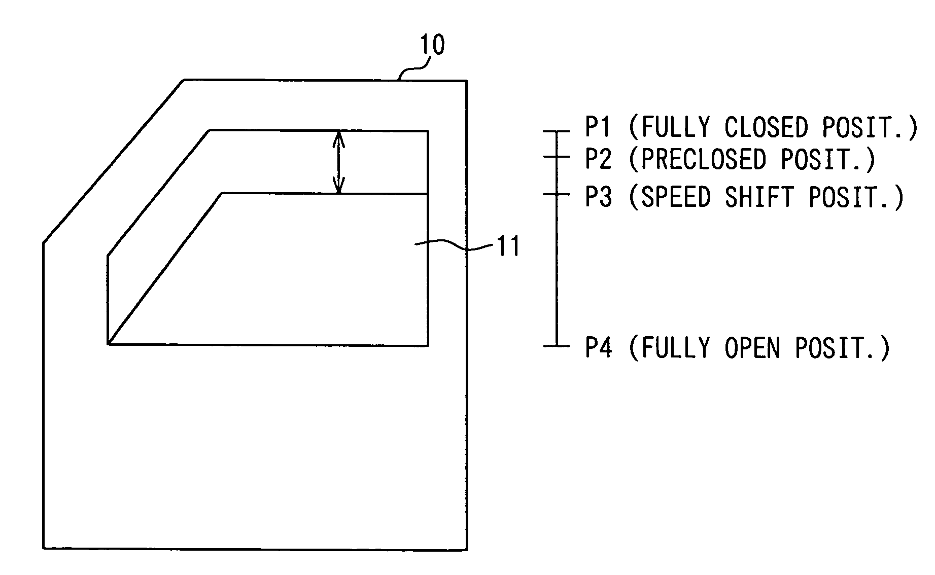
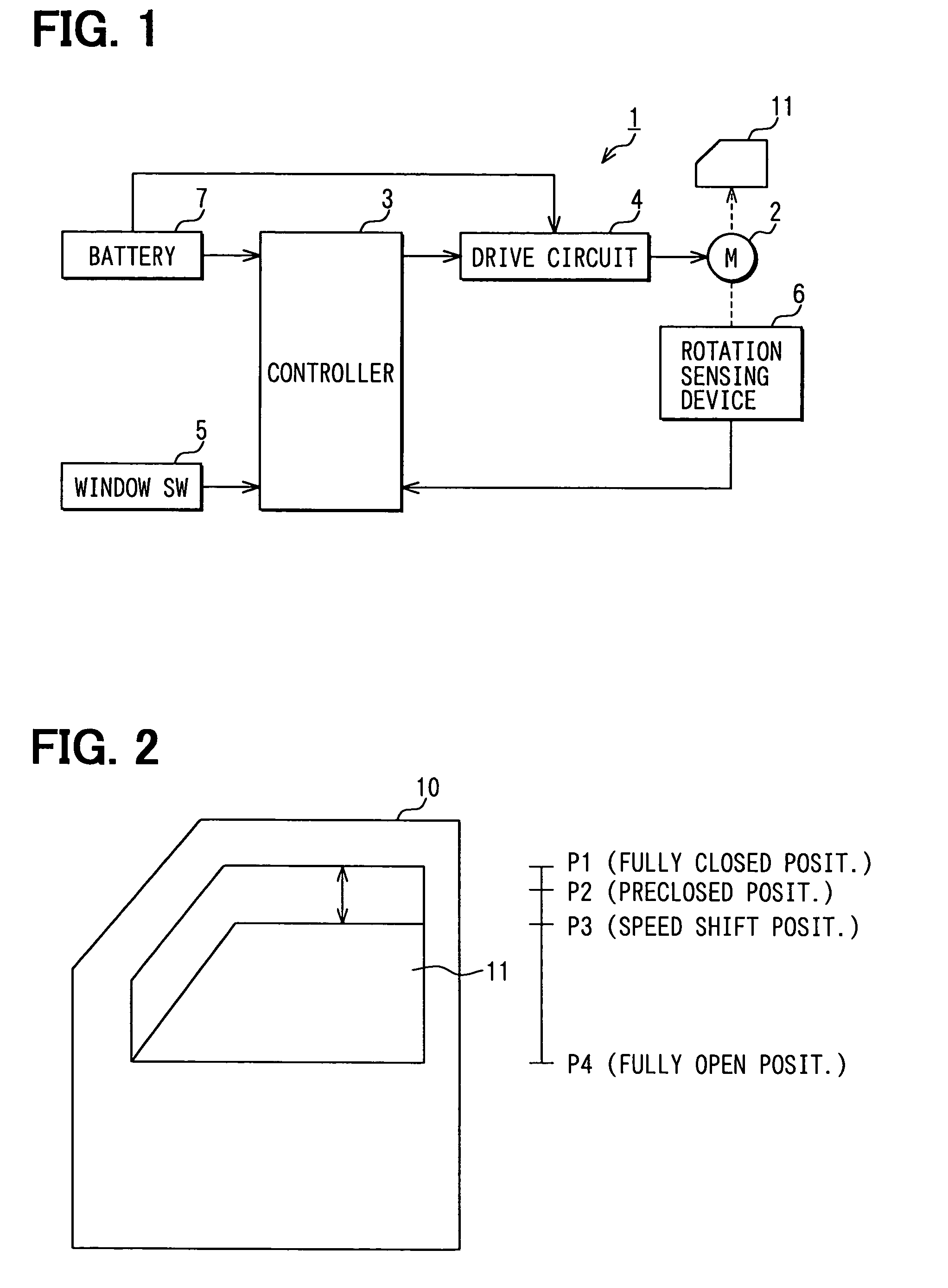
[0023]In a power window system (a closing member control system) 1 of FIG. 1, a window glass 11, which serves as a closing member, is arranged in a vehicle side door 10 of FIG. 2. The window glass 11 is raised or lowered, i.e., is closed or opened through rotation of a drive motor 2. The power window system 1 includes the drive motor 2, a controller 3, a drive circuit 4, a window switch (window SW) 5 and a rotation sensing device 6, each of which is arranged at a corresponding predetermined position in the vehicle. The controller 3 constitutes a pinching control means, a position sensing means and a motor output control means. The window switch 5 serves as a closing / opening operation commanding means. The rotation sensing device 6 also constitutes the position sensing means. Required electric power is supplied to the controller 3 from a vehicle battery 7. Also, required electric power ...

second embodiment

[0043]A second embodiment of the present invention will be described with reference to FIGS. 5 and 6. In the second embodiment, the duty ratio shifting process of the controller 3 slightly differs from that of the first embodiment. Thus, the following description will be mainly focused on the duty ratio shifting process of the controller 3.

[0044]The controller 3 supplies the electric power to the drive motor 2 at the duty ratio (Duty) of 100% to operate the drive motor 2 at the normal speed throughout the entire operational interval (i.e., a P1 to P4 interval) in the opening operation of the window glass 11. Furthermore, with reference to FIG. 5, the controller 3 supplies the electric power to the drive motor 2 at the duty ratio (Duty) of 100% to operate the drive motor 2 at the normal speed in the interval from the fully open position P4 to the speed shift position P3 (the P4 to p3 interval). Also, the controller 3 supplies the electric power to the drive motor 2 at the duty ratio ...

third embodiment

[0060]A third embodiment of the present invention will be described with reference to FIGS. 7 and 8. In the third embodiment, the duty ratio shifting process of the controller 3 slightly differs from that of the first embodiment. Thus, the following description will be mainly focused on the duty ratio shifting process of the controller 3.

[0061]The controller 3 of the third embodiment supplies the electric power to the drive motor 2 at the duty ratio (Duty) of 100% throughout the entire operational interval (i.e., a P1 to P4 interval) in the opening operation of the window glass 11.

[0062]Furthermore, with reference to FIG. 7, the controller 3 supplies the electric power to the drive motor 2 at the duty ratio (Duty) of 100% to operate the drive motor 2 at the normal speed in the interval from the fully open position P4 to the speed shift position P3 (the P4 to P3 interval) and also in the interval from the preclosed position P2 to the fully closed position P1 (the P2 to P1 interval) i...


PUM


Abstract

A controller reduces an output of the drive motor when a window glass reaches a speed shift position, which is between a fully open position and a fully closed position of the window glass, in a closing operation of the window glass. The controller increases the output of the drive motor based on a position signal, which indicates that the position of the closing member in the closing operation is in a preclosed position located on a fully closed position side of the speed shift position. The preclosed position is located in a pinch-monitoring disabled zone, in which the monitoring of the pinching of the object through the controller is disabled.

Description

CROSS REFERENCE TO RELATED APPLICATION[0001]This application is based on and incorporates herein by reference Japanese Patent Application No. 2003-278381 filed on Jul. 23, 2003.BACKGROUND OF THE INVENTION[0002]1. Field of the Invention[0003]The present invention relates to a closing member control system, such as a power window system for closing and opening a vehicle window glass or a sunroof system for closing and opening a roof glass.[0004]2. Description of Related Art[0005]One previously proposed vehicle power window system has a protective function for limiting pinching of an object by a window glass. In order to reduce the pinching load applied to the pinched object from the window glass, the vehicle power window system changes the closing speed of the window glass from the normal speed to a reduced speed at a location near a fully closed position of the window glass until the window glass reaches the fully closed position. Such a power window system is disclosed in, for examp...

Claims


Application Information

Patent Timeline
Patent Type & Authority Patents(United States)
IPC IPC(8): G05B5/00E05F15/10E05F15/16H02H7/085H02P3/00
CPCH02H7/0851E05Y2900/55E05F15/695E05F15/41E05F15/665
Inventor YAMAMOTO, MOTOYA
Owner DENSO CORP
Why Eureka
Try Eureka