Current sense shunt resistor circuit

Inactive Publication Date: 2005-01-27
INTERNATIONAL RECTIFIER COEP
View PDF4 Cites 21 Cited by
  • Summary
  • Abstract
  • Description
  • Claims
  • Application Information

AI Technical Summary

Benefits of technology

[0010] The data from Table 2 indicates that as the application current increases, the dynamic range available through the appropriately sized shunt resistor decrease

Problems solved by technology

Because this technique inherently requires a voltage drop, there is often a large amount of power dissipated in the resistance with large current flows.
With the limited dynamic range resulting from the lowered shunt resistance, the accuracy and precision of voltage measurements is degraded.
For example, the thermal resistance of the shunt is fairly high causing an

Method used


Image

  • Current sense shunt resistor circuit
  • Current sense shunt resistor circuit
  • Current sense shunt resistor circuit

Examples


Embodiment Construction

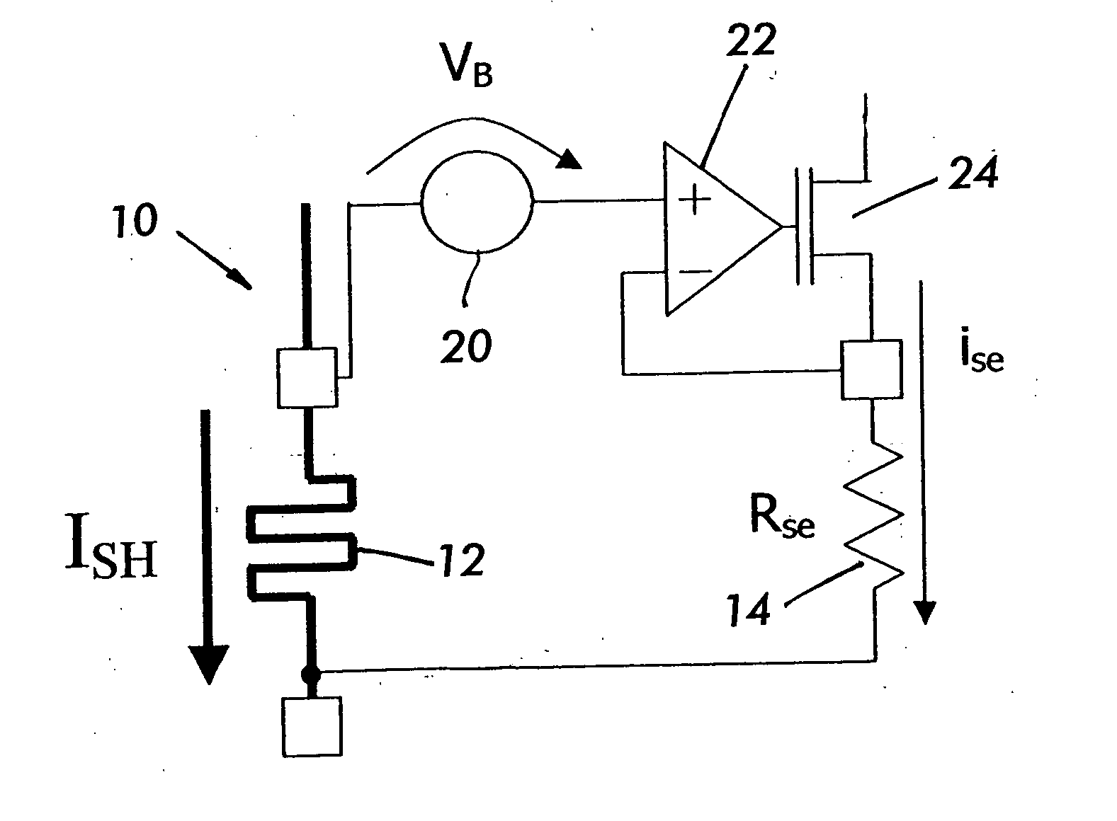
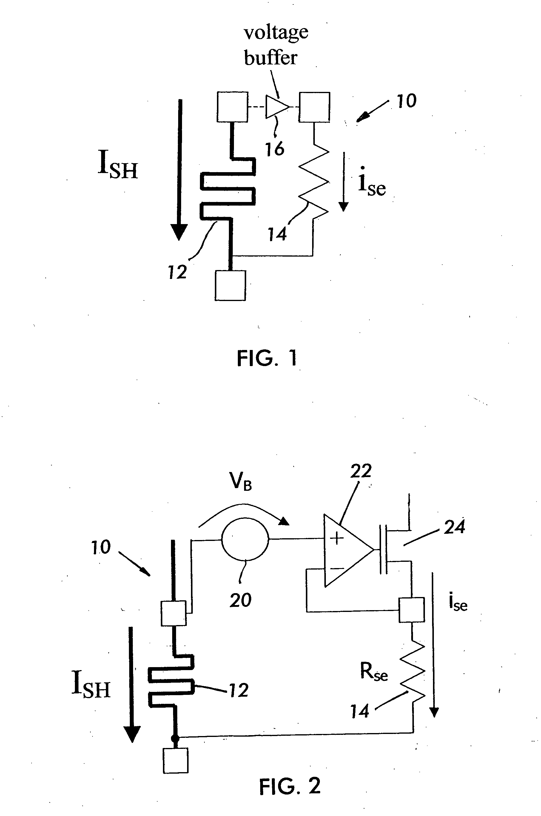
[0022] Referring now to FIG. 1, the current sense and shunt resistor circuit is shown generally as sensing circuit 10. Circuit 10 includes a current shunt 12 that measures current in an output circuit by driving a voltage across shunt 12. Circuit 10 is in the form of a current divider that provides two parallel paths for shunt current, including a path through a sensing resistor 14. Circuit 10 includes a voltage buffer 16 to control current between the two parallel shunt paths. By making sense resistor 14 have the same voltage as shunt resistor 12, sense resistor current ise is determined according to the following equation. ise-ISH·RSH0Rse0=ISHG(1)

[0023] In equation 1, ise is the sense resistor current, ISH is the shunt resistor current, RSH is the shunt resistor resistance value, Rse is the sense resistor resistance value and G is the gain ratio determined by the values of the shunt and sense resistors. Circuit 10 can be arranged and operated so that a value for G can be chosen t...


PUM


Abstract

Current through a wire is sensed with a shunt resistor and a sense resistor in a current divider circuit. The values of the shunt resistor and sense resistor are related to provide a specified gain ratio to increase a dynamic range of current measurement. The sense resistor is a trimmable resistor, the configuration of which can be discerned from a look-up table based on a level of precision needed for current measurement. The two resistors can also be related by thermal coefficients to improve linearity of current measurements.

Description

BACKGROUND OF THE INVENTION [0001] 1. Field of the Invention [0002] The present invention relates generally to sensing output current in an electrical circuit. The present invention relates more particularly to a shunt resistor connected to an electrical circuit output to measure the current of the output. [0003] 2. Description of Related Art [0004] A number of electrical applications, in particular power applications, take advantage of output current sensing to provide feedback control for the electrical circuit or system. Typically, the output current is sensed by measuring a voltage drop across a highly precise resistance to thereby determine the current flowing through the resistance related to the measured voltage drop. Because this technique inherently requires a voltage drop, there is often a large amount of power dissipated in the resistance with large current flows. Indeed, because power equals the resistance times the current squared, increasing current determines an incre...

Claims


Application Information

Patent Timeline
IPC IPC(8): G01R1/20G01R19/00
CPCG01R19/0092G01R1/203
Inventor GRASSO, MASSIMOTORTI, ALDOMERELLO, ANDREAALEKSANDRAVICIUS, JONAS
Owner INTERNATIONAL RECTIFIER COEP
Why Eureka
Try Eureka