Complementary signal generator

a technology of complementary signal and generator, applied in the direction of generating/distributing signals, pulse techniques, instruments, etc., can solve the problems of inaccurate timing provided for charging or discharge capacitors, inaccurate cancellation of offsets,

Inactive Publication Date: 2005-01-27
LAPIS SEMICON CO LTD
View PDF9 Cites 28 Cited by
  • Summary
  • Abstract
  • Description
  • Claims
  • Application Information

AI Technical Summary

Problems solved by technology

A problem arises in that when, for example, the offset cancel circuit is driven by the complementary signals shifted in inversion timing as mentioned above, the timing provided to charge or discharge the capacitor becomes inaccurate, so that the cancellation of the offset is not performed accurately.

Method used


Image

  • Complementary signal generator
  • Complementary signal generator
  • Complementary signal generator

Examples


first preferred embodiment

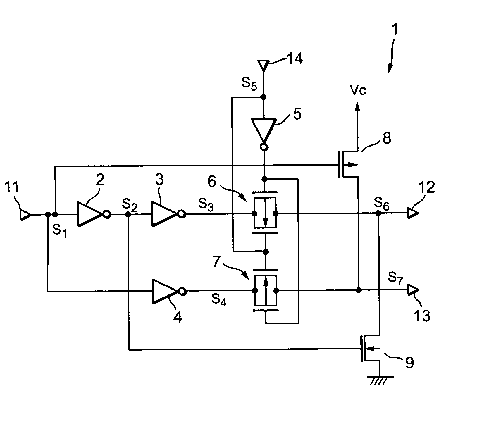
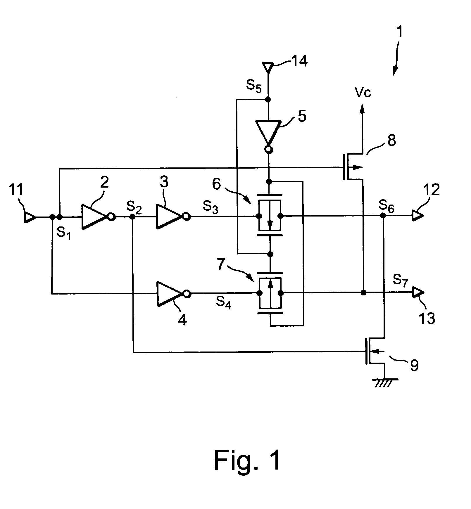
FIG. 1 is a circuit diagram showing a configuration of a complementary signal generator according to a first preferred embodiment based on the present invention.

As shown in the same figure, an input part 11 of the complementary signal generator 1 is connected to respective input parts of inverters 2 and 4 which share impedance conversion and to the gate of a P channel type FET 8. An output part of the inverter 2 is connected to an input part of an inverter 3 and to the gate of an N channel type FET 9.

An analog switch 6 comprises a pair of FETs of a P channel type and an N channel type, which is connected in parallel. An output part of the inverter 3 is connected to one connecting terminal of the analog switch 6, and a positive-phase signal output part 12 of the complementary signal generator 1 is connected to the other connecting terminal thereof. An output part of the inverter 4 is connected to one connecting terminal of an analog switch 7 identical in configuration to the anal...

second preferred embodiment

A second preferred embodiment showing a complementary signal generator of the present invention will next be described below with reference to the accompanying drawings.

FIG. 3 is a circuit diagram showing a configuration of a complementary signal generator 21 illustrative of a second preferred embodiment based on the present invention.

As shown in the same figure, an input part 31 of the complementary signal generator 21 is connected to respective input parts of inverters 22 and 24 which share impedance conversion. An output part of the inverter 22 is connected to an input part of an inverter 23. An output part of the inverter 23 is connected to respective one connecting terminals of analog switches 27 and 29 each made up of a pair of P channel and N channel type FETs connected in parallel. Similarly, an output part of the inverter 24 is connected to respective one connecting terminals of analog switches 28 and 30 each made up of a pair of P channel and N channel type FETs connec...


PUM


Abstract

A complementary signal generator, for outputting complementary positive-phase and antiphase signals that vary between a first logical value and a second logical value, which includes a signal forming unit for outputting a positive-phase intermediate signal being in phase with an input signal varying between the first logical value and the second logical value, and an antiphase intermediate signal antiphase to the input signal. The generator also includes a first connecting means for simultaneously transferring the second logical value of the positive-phase intermediate signal and the first logical value of the antiphase intermediate signal to a positive-phase signal output part and an antiphase signal output part in synchronism with a state change of the input signal from the first logical value to the second logical value.

Description

BACKGROUND OF THE INVENTION 1. Field of the Invention The present invention relates to a complementary signal generator for outputting a positive-phase signal and an antiphase signal complementary to each other. This application is counterpart of Japanese patent applications, Serial Number 278802 / 2003, filed Jul. 24, 2003, the subject matter of which is incorporated herein by reference. 2. Description of the Related Art As this type of complementary signal generator, there is known one which outputs complementary signals formed by input and output signals of inverters to switch, by complementary signals to be outputted, a plurality of switches connected so as to switch the other end of a capacitor whose one end is connected to an inversion input terminal thereof between a non-inversion input terminal and an output terminal with a view toward canceling an offset of a voltage follower, for example (e.g., refer to Patent Document 1). As the complementary signal generator as well,...

Claims


Application Information

Patent Timeline
Patent Type & Authority Applications(United States)
IPC IPC(8): H03K5/12H03K5/151
CPCH03K5/151
Inventor HONDA, TAKASHI
Owner LAPIS SEMICON CO LTD
Why Eureka
Try Eureka