Electronic watermark embedding device, electronic watermark detection device, electronic watermark embedding method, and electronic watermark detection method

a technology of electronic watermark and embedding device, applied in the field of electronic watermark embedding/detection technology, can solve the problems of difficult identification of the location of changes and low detection accuracy in cases

Active Publication Date: 2005-01-27
OKI ELECTRIC IND CO LTD
View PDF23 Cites 56 Cited by
  • Summary
  • Abstract
  • Description
  • Claims
  • Application Information

AI Technical Summary

Problems solved by technology

In the case where the changes are handwritten or the like, because this is so different from the printed texts, the location of the changes can be quickly identified, but in the case where overwriting and printing are done in the same font as the original, it is difficult to identify the location of the changes.
Prior art examples [1]-[4] include methods in which a determination as to whether there has been alteration can be made when the information embedded in the printed document can no longer be correctly read, but detection accuracy is not high in cases where the information cannot be read because the surface of the paper is smudged, or when there is static at the time of printing.

Method used


Image

  • Electronic watermark embedding device, electronic watermark detection device, electronic watermark embedding method, and electronic watermark detection method
  • Electronic watermark embedding device, electronic watermark detection device, electronic watermark embedding method, and electronic watermark detection method
  • Electronic watermark embedding device, electronic watermark detection device, electronic watermark embedding method, and electronic watermark detection method

Examples


first embodiment

(First Embodiment)

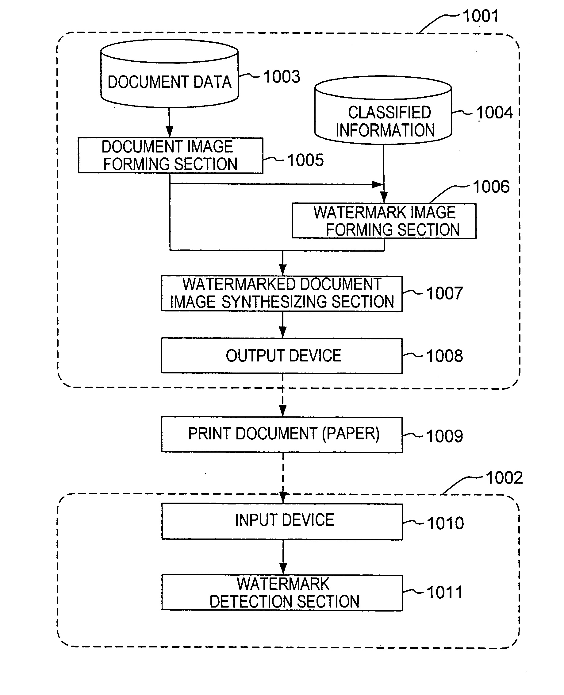
FIG. 1 is an explanatory diagram showing the structure of the electronic watermark embedding device and the electronic watermark detection device of the first embodiment of this invention. First, the electronic watermark detection device 1001 will be described.

(Electronic Watermark Embedding Device 1001)

The electronic watermark embedding device 1001 forms document images based on document data 1003 and classified information 1004 which is embedded in the document, and prints it on a paper medium. The document data 1003 is data including font information and layout information, and is data created by document creation tools and the like such as word processing software and the like. Also, the classified information 1004 is information which is embedded in the forms other than text and may be various types of data such as text, image, and sound.

As shown in FIG. 1, the electronic watermark embedding device 1001 comprises the document image forming section 1005, ...

second embodiment

(Second Embodiment)

FIG. 20 is an explanatory diagram showing the structure of the electronic watermark embedding device and the electronic watermark detection device of the second embodiment of this invention. The difference between this and the first embodiment is that, the electronic watermark detection device 2002 also has a text deletion alteration detection section 2012. Here the structure and operation of the electronic watermark embedding device 1001 is the same as that of the first embodiment.

(Text Deletion Alteration Detection Section 2012)

The text deletion alteration detection section 2012 is the portion where the process is carried out for detecting the presence and location of alteration in the case where text portion of the print document 1009 has been altered with by deletion with correction fluid and the like.

FIG. 21 is a flowchart showing the operation of the text deletion alteration detection section.

It is assumed that the alteration is the case where text po...

third embodiment

(Third Embodiment)

FIG. 26 shows the structure of the third embodiment of this invention. The difference between this and the first embodiment is that, the electronic watermark embedding device 3001 also has the embedded signal number recording section 3012, and the electronic watermark detection device 3002 also has the embedded signal number detecting section 3013, the filter output value calculating section 3014, the optimum threshold value determining section 3015, the detection signal counter 3016 and the alter determination section 3017. Here the operation of other structural elements is the same as those of the first embodiment.

(Embedded Signal Number Recording Section 3012)

The embedded signal number recording section 3012 is the section for recording the number of signals embedded in the watermark image in the image itself. This signal number changes depending on the number of characters and layout of the document image of the original text.

(Embedded Signal Number Detec...


PUM


Abstract

To provide an electronic watermark embedding device for improving accuracy when classified information is being detected. The watermark image forming section 1006 creates a watermark image based on classified information 1004 with reference to the document image. For the document image, embedding regions for embedding a dot pattern which is identifiable as a prescribed symbol by a prescribed filter are detected, and a determination is made as to whether or not the proportion of the text region to the embedding region is less than or equal to a prescribed threshold value, and if the proportion of the text region is less than or equal to the prescribed threshold value, a prescribed number of dot patterns in which a symbol formed of at least a portion of the classified information is identifiable (symbol unit) is embedded in a region where the embedding region and the text region do not overlap. Because classified information is embedded only in regions that do not overlap with the text region by using the document image as a reference, embedding of classified information can be ensured regardless of the form of the original document.

Description

BACKGROUND OF THE INVENTION This invention pertains to an electronic watermark embedding / detection technology for determining whether or not changes have been made to an original, and for specifying the location of the changes, when changes such as text string addition or deletion have been made to a printed document which has been watermarked, by inputting the document into a computer using a scanner or the like, and then processing the document. DESCRIPTION OF THE RELATED ART An “electronic watermark” is information for preventing duplication or counterfeiting, or classified information which is embedded in image or document data or the like in a form which is not visible to the human eye. This watermarking presumes that all recording and transfer of data occurs in an electronic medium, and because deterioration or loss of information embedded by watermarking cannot occur, the information can be detected with certainty. Similarly, in order to prevent a document that has been pri...

Claims


Application Information

Patent Timeline
Patent Type & Authority Applications(United States)
IPC IPC(8): G06T1/00H04N1/44
CPCG06T2201/0051G06T1/0028
Inventor SUZAKI, MASAHIKO
Owner OKI ELECTRIC IND CO LTD
Why Eureka
Try Eureka