Wheel support bearing assembly

a bearing and wheel technology, applied in the direction of bearing unit rigid support, mechanical equipment, transportation and packaging, etc., can solve the problems of hub axle, inability to perform smoothly and efficiently the bolt fastening work, and bulky size of the hub axle, so as to reduce the weight of the wheel support bearing assembly

Inactive Publication Date: 2005-01-27
NTN CORP
View PDF2 Cites 54 Cited by
  • Summary
  • Abstract
  • Description
  • Claims
  • Application Information

AI Technical Summary

Benefits of technology

[0019] In view of the foregoing, the present invention has for its object to reduce the weight of the wheel...

Problems solved by technology

However, with the wheel support bearing assembly in which the wheel mounting hub flange 72 integral or rigid with the hub axle 62 has the substantially round shape as discussed above, it has been found that when the wheel support bearing assembly is to be bolted to the vehicle body structure through the vehicle body fixture 64b, the bolt fastening work cannot be performed smoothly and efficiently as the presence of the hub flange 72 in the path of access of a bolt fastening tool interferes with such bolt fastening tool.
Also, in view of the fact that the hub flange 72 is formed to the substantially round shape, the hub axle 62 tends to become bulky in size and, even though the remaining non-ribbed portions 72b of the hub flange 72 are each tailored to have a relatively reduced wall thickness, reduction in weight of the wheel support bearing assembly as a whole is not still satisfactory.
However, the wheel support bearing assembly disclosed in the above mentioned publication has been found that the are of portions to be depleted is still insufficient and, therefore, the...

Method used


Image

  • Wheel support bearing assembly
  • Wheel support bearing assembly
  • Wheel support bearing assembly

Examples


second embodiment

[0120] shown in FIGS. 5 and 6, the protective cover 19 concurrently providing an area which the contact type seal member 8 engages slidingly is mounted on the hub axle 2 with the covering area 19b covering the gap or depleted space in the hub flange 12 delimited between the neighboring rib or spider arms 13. Accordingly, any undesirable ingress of water from the outboard side, i.e., from outside of the wheel support bearing assembly 1A can advantageously be avoided, which ingress would result in because of the unique shape of the hub flange 12 comprised of the plural ribs or spider arms 13. Also, since the protective cover 19 concurrently serves as the seal contact area with which the seal member 8 engages slidingly, the use of the protective cover 19 will not adversely affect the intended weight reduction.

[0121] The wheel support bearing assembly 1B according to a third preferred embodiment of the present invention is shown in FIGS. 7A and 7B. While FIG. 7B illustrates the wheel s...

third embodiment

[0124] According to the present invention shown in and described with reference to FIGS. 7A and 7B, since the knuckle pilot area 23 is composed of the circumferentially spaced knuckle pilot segments 23a, the weight of the knuckle pilot area 23 is advantageously reduced to thereby achieve a further weight reduction of the wheel support bearing assembly 1B as a whole.

[0125] Other structural features of the wheel support bearing assembly 1B than those described above are similar to those of the wheel support bearing assembly 1 in the foregoing embodiment and, therefore, the details thereof will not be reiterated for the sake of brevity, noting that component parts shown in FIGS. 7A and 7B, but similar or identical to those shown in FIGS. 1 and 2 are designated by like reference numerals employed in FIGS. 1 and 2.

[0126] It is to be noted that in the embodiment shown in and described with reference to FIGS. 7A and 7B the knuckle pilot area 23 has been shown and described as circumferent...

first embodiment

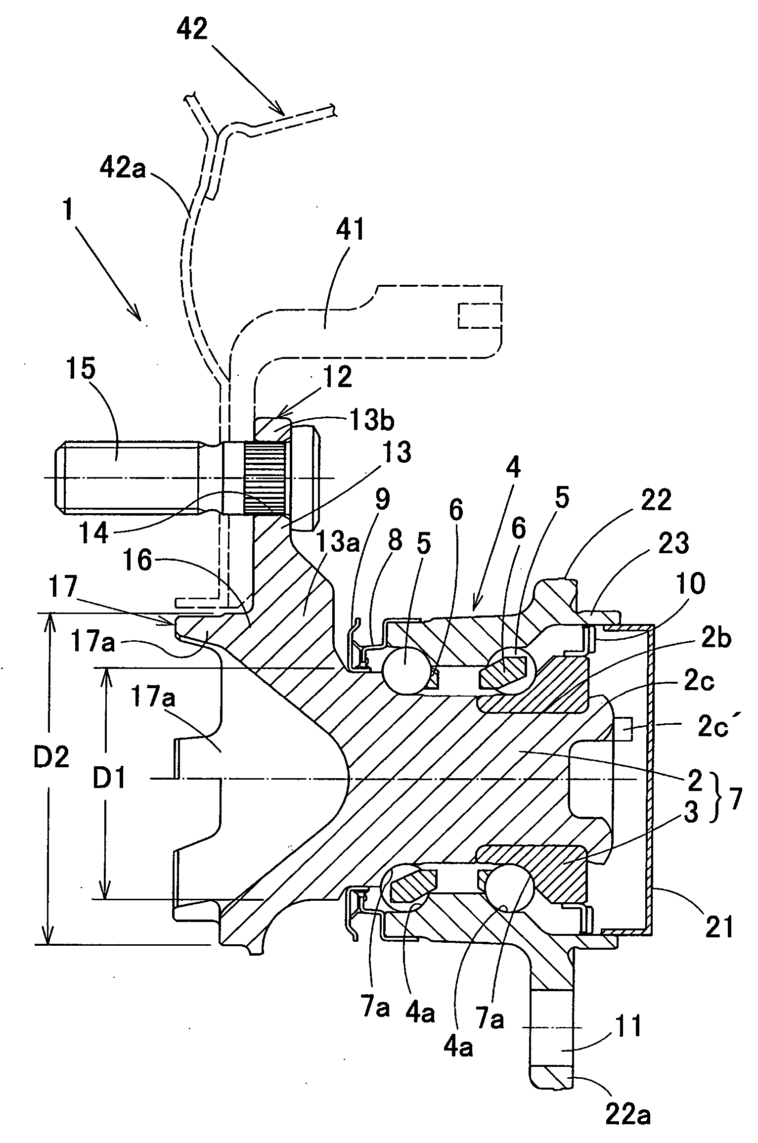
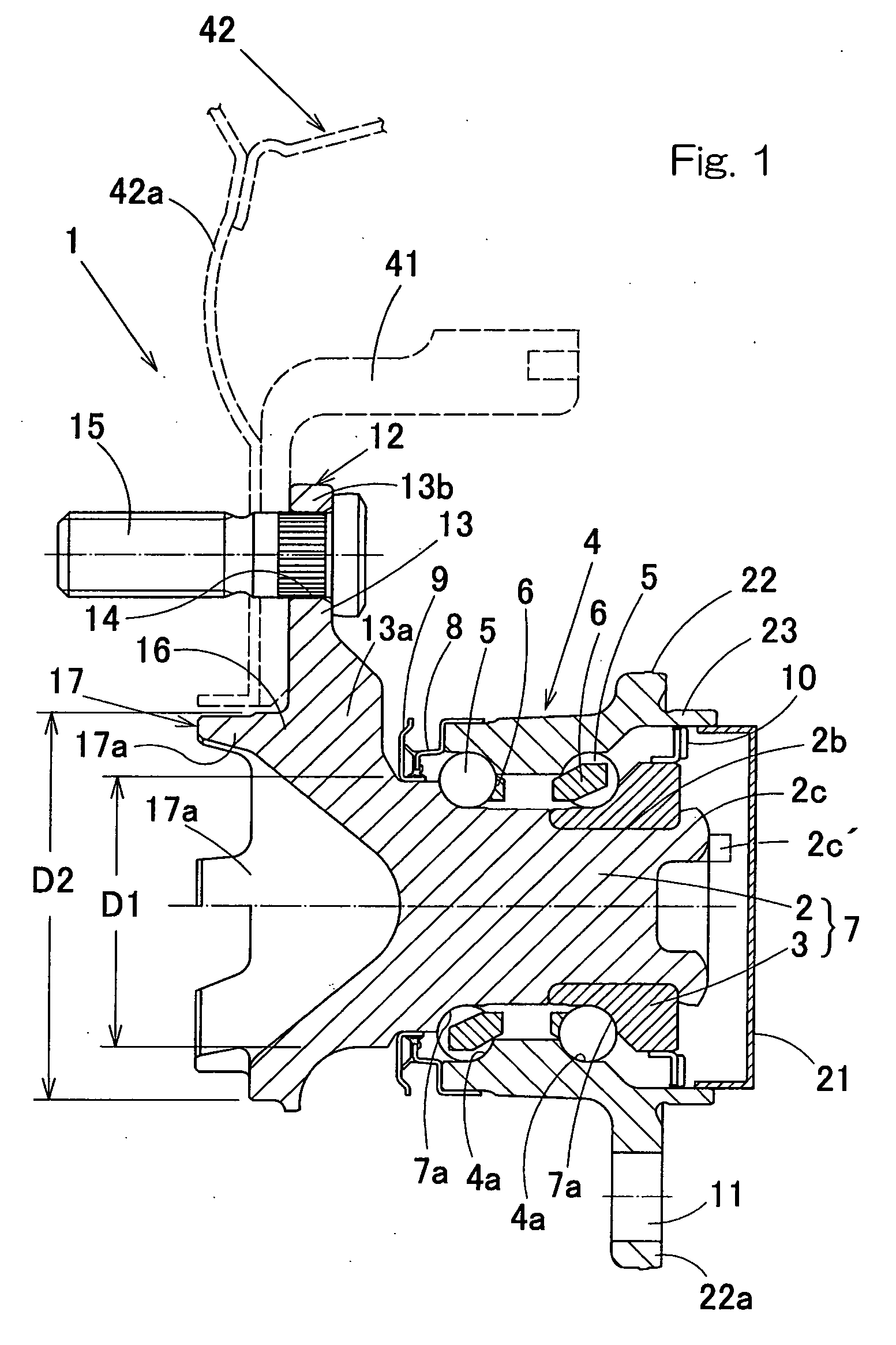
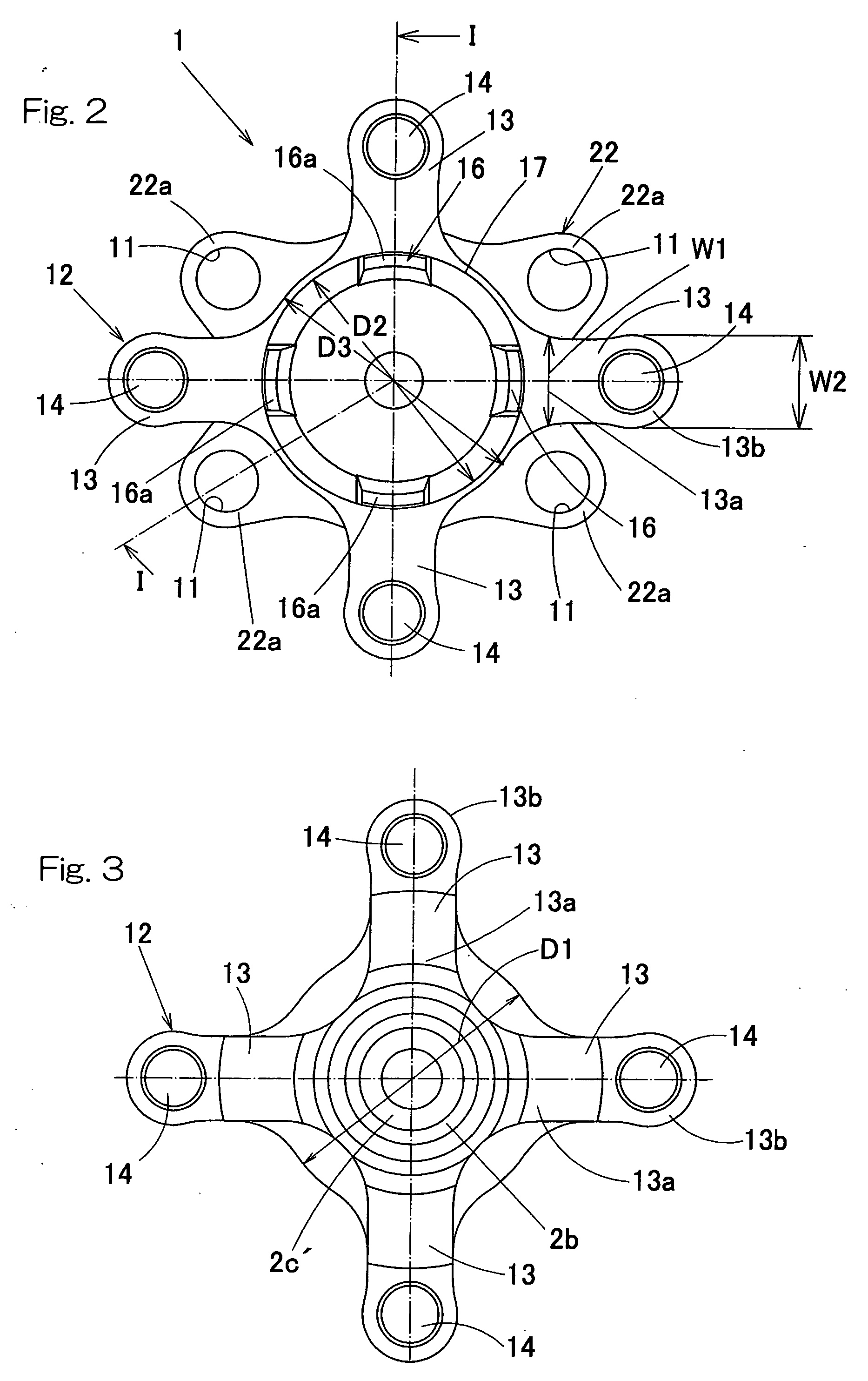
[0128] FIGS. 8 to 9B illustrate the wheel support bearing assembly 1C according to a fourth preferred embodiment of the present invention. The wheel support bearing assembly 1C shown therein is similar to the wheel support bearing assembly 1 according to the present invention, except that in this embodiment the brake pilot area 16 is formed with a plurality of circumferentially spaced cutouts, leaving a corresponding number of brake pilot segments 16a that are spaced from each other in a direction circumferentially thereof. The circumferentially spaced cutouts referred to above are formed so as to continue axially from the wheel pilot area 17 to the brake pilot area 16, with the circumferentially spaced wheel pilot segments 17a and the circumferentially spaced brake pilot segments 16a being consequently continued together in the form of respective single axial projections.

[0129] It is to be noted that division of the brake pilot area 16 to provide the brake pilot segments 16a may be...


PUM


Abstract

To reduce the weight of the wheel support bearing assembly without sacrificing the strength, the wheel support bearing assembly for rotatably supporting a vehicle wheel relative to a vehicle body structure includes a hub axle (2) formed with a radially outwardly extending hub flange (12). This hub flange (12) has an inner peripheral portion and a remaining wall portion other than the inner peripheral portion, and the remaining wall portion thereof is constituted by a plurality of radially outwardly extending ribs (13) each formed with a bolt insertion hole (14). The hub axle (2) also includes a brake pilot area (16) extending outwardly from an outboard face of the hub flange (12) for guiding an inner peripheral surface of the brake rotor (41). At least the root diameter (D1) of at least an inboard face of each rib (13) is chosen to be equal to or smaller than the outer diameter (D2) of the brake pilot area (16).

Description

BACKGROUND OF THE INVENTION [0001] 1. Field of the Invention The present invention relates to a wheel support bearing assembly for use in automotive vehicles. [0002] 2. Description of the Prior Art [0003] As is well known to those skilled in the art, the need to reduce the weight of component parts of automotive vehicles has now been pressing in order to improve the mileage, and this is particularly true of wheel support bearing assemblies employed in the automotive vehicles. [0004] The wheel support bearing assembly of a hub unit type is well known in the art, which is a combined hub and bearing assembly including a wheel support bearing concurrently serving as a wheel hub. The wheel support bearing assembly of a hub unit type currently utilized in association with automotive vehicle wheels is shown in FIG. 19 and includes a hub axle 62 having an outboard end formed with a radially outwardly extending hub flange 72 for the support of a corresponding vehicle wheel and also having a ...

Claims


Application Information

Patent Timeline
IPC IPC(8): B60B27/00B60B35/18F16C33/58
CPCB60B27/00F16C19/186F16C2326/02Y02T10/86F16C33/7826F16C35/06F16C33/586F16C2240/70F16C2240/40F16C33/58B60B35/18
Inventor NIWA, TSUYOSHISUZUKI, SHOUGOASAI, TAKAYUKIOHTSUKI, HISASHITAKUBO, TAKAYASU
Owner NTN CORP
Why Eureka
Try Eureka