Self-piercing rivet fastening device and die used by the fastening device

a fastening device and rivet technology, applied in the direction of threaded fasteners, fastening means, screws, etc., can solve the problems of uneven fastening strength and weakening of fastening strength, and achieve the effect of reducing or eliminating the constraints on the fastened members and weakening the fastening strength

Inactive Publication Date: 2005-01-27
NEWFREY +1
View PDF99 Cites 31 Cited by
  • Summary
  • Abstract
  • Description
  • Claims
  • Application Information

AI Technical Summary

Benefits of technology

[0010] Therefore, the first purpose of the present invention is to provide a self-piercing rivet fastening device that reduces or eliminates the constraints on the fastened members in the rivet-driving direction. If the self-piercing rivet and die are not replaced when the thickness and the number of fastened members changes, a gap opens both between the self-piercing rivet and the fastened member and between the fastened members themselves. This weakens the fastening strength or leads to uneven fastening strength. The fastened member near the head of the self-piercing rivet is also warped. Therefore, the second purpose of the present invention is to provide a self-piercing rivet fastening device and a die for a self-piercing fastening device that can fasten the fastening members without the seal being broken, without gaps opening between the self-piercing rivet and the fastening members or between fastening members themselves, without warping the fastened member near the head of the rivet, and without having to change the self-piercing rivet (to a rivet with a different overall length) or the die (to a die with a different recess diameter or recess depth) even when the thickness or the number of fastened members is changed.
[0012] In this self-piercing rivet fastening device, the center pin on the die main body comes into contact with the receiving-end fastened member on the die end when the tip of the legs on the self-piercing rivet penetrate the fastened member on the receiving end adjacent to the die, but the center pin does not act on the fastened member on the receiving end. Consequently, the legs of the self-piercing rivet penetrate the fastened member on the receiving end without expanding outward. When the legs of the rivet begin to penetrate the fastened member on the receiving end, the center pin rises up and the tip of the legs on the rivet begins to expand outward radially to a significant degree. The expansion provides an adequate amount of undercut. The amount of undercut even provides enough joining force when the thickness of the fastened member on the receiving end is less than {fraction (1 / 2)} the thickness of the other fastened member (i.e., the fastened member on the punch end). This reduces or eliminates the constraints on the fastened members in the rivet-driving direction. Unlike fastening devices of the prior art, the effort required to reverse the fastening device or reverse the fastened members is reduced or eliminated. Consequently, the fastening process can be performed quickly. Fastening can also be performed in directions impossible using a fastening device of the prior art. This eliminates constraints on fastening positions, and expands the places or positions where a self-piercing rivet can be applied.

Problems solved by technology

This weakens the fastening strength or leads to uneven fastening strength.

Method used


Image

  • Self-piercing rivet fastening device and die used by the fastening device
  • Self-piercing rivet fastening device and die used by the fastening device
  • Self-piercing rivet fastening device and die used by the fastening device

Examples


Embodiment Construction

[0033] The following is an explanation of embodiments of the present invention with reference to the drawings. First, embodiments of the present invention corresponding to the first purpose will be explained.

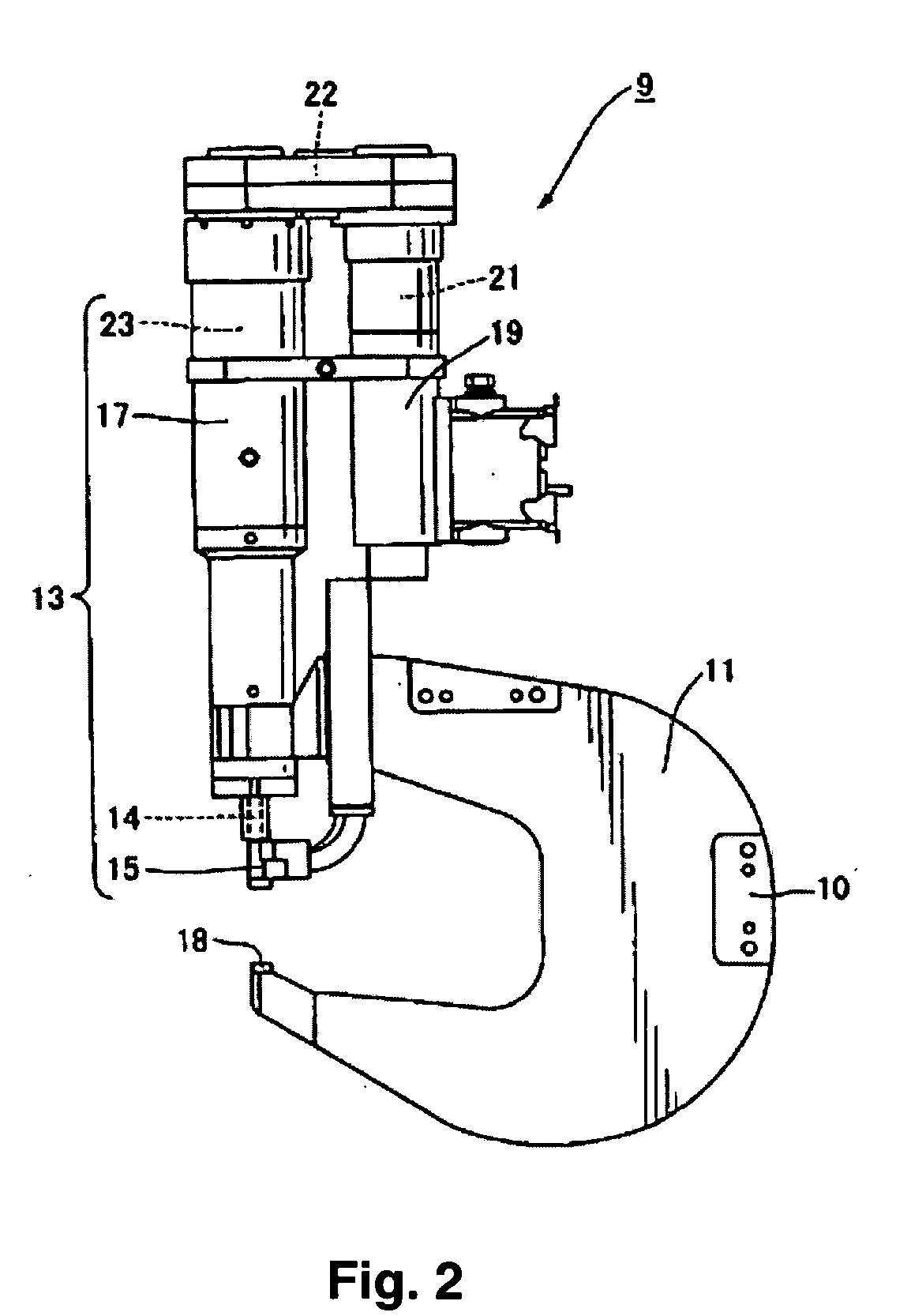
[0034]FIG. 2 is a simplified diagram of the entire self-piercing rivet fastening device 9 in the first embodiment of the present invention. In FIG. 2, the self-piercing rivet device 9 has a C-shaped frame 11 with a connector 10 to an articulated robot arm (not shown). The C-shaped frame 11 is rigid with an integrated upper horizontal arm portion, a vertical arm portion attached to the connector 10, and a lower horizontal arm portion. The fastening mechanism 13 constituting the main portion of the self-piercing rivet fastening device is attached to the end of the upper horizontal arm portion of the C-shaped frame 11.

[0035] A punch 14 is attached to the end (lower end in FIG. 2) of the fastening mechanism 13 so as to be able to move freely, and a receiver portion 15 is attached ...


PUM

PropertyMeasurementUnit
diameteraaaaaaaaaa
pressureaaaaaaaaaa
of movementaaaaaaaaaa

Abstract

The die 18 of the self-piercing rivet fastening device is equipped with a center pin 25 for receiving the hollow section of the legs 5 on the self-piercing rivet 1 and a die main body 27 having a cavity 26 for guiding the distortion of the tip of the legs on the self-piercing rivet outward radially on the outer periphery of the center pin 25. The center pin 25 and the die main body 27 are supported so as to move relatively freely in the axial direction of the center pin 25 towards the punch 14. It also has a plate spring 41 allowing the center pin 25 to move relative to the die main body 27 so the center pin 25 comes into contact with the die end surface of the fastened member 3 on the receiving end when the self-piercing rivet 1 under pressure from the punch 14 is driven into the fastened members 2, 3 and the tip of the legs begins to pierce the fastened member 3 on the receiving end. This reduces or eliminates the constraints on the fastened members in the rivet-driving direction.

Description

CROSS-REFERENCE TO RELATED APPLICATIONS [0001] This application is a continuation of a PCT Application No. PCT / JP02 / 13746, filed Dec. 27, 2002, which claims priority to Japanese Patent Application No. 2001-397363, filed Dec. 27, 2001 and Japanese Patent Application No. 2001-395691, filed Dec. 27, 2001, which are incorporated by reference herein.FIELD OF THE INVENTION [0002] The present invention relates to a self-piercing rivet fastening device and a die used on this fastening device and, more specifically, to a self-piercing rivet fastening technology using a self-piercing rivet to fasten at least two but possibly also three or more fastened members such as panels (or panels and components) together during the panel assembly operation (such as the aluminum body assembly operation) in automotive assembly. BACKGROUND OF THE INVENTION [0003] One example of a self-piercing rivet fastening device is described in Japanese Examined Patent Application Disclosure [Kokoku] No.8-505087. An ex...

Claims


Application Information

Patent Timeline
Patent Type & Authority Applications(United States)
IPC IPC(8): B21J15/02B21J15/10B21J15/36
CPCB21J15/025B21J15/36B21J15/10B21J15/04
Inventor IWATSUKI, SHUICHIROFUJITA, MASASHINAITOH, NOBUHARUASAOKA, TATSUOYAMAZAKI, MASAKI
Owner NEWFREY
Why Eureka
Try Eureka