
Electronic endoscope device

Inactive Publication Date: 2005-01-27
OLYMPUS CORP
View PDF8 Cites 46 Cited by
  • Summary
  • Abstract
  • Description
  • Claims
  • Application Information

AI Technical Summary

Benefits of technology

[0009] According to the first aspect of the present invention, a restricting unit is included for restricting processing to be performed by the signal processing unit according to the result of detecting performed by the detector. For example, the type of solid-state imaging device included in the electronic endoscope is detected. Depending on the detected type of solid-state imaging device, processing is restricted for fear unnecessary processing may be performed. In this case, presentation of the processing feature may be restricted so that the fact that the processing feature is invalid can be readily recognized. Otherwise, depending on whether an expansion board is present, the indication of a feature implemented on the expansion board may be restricted. Thus, ease of use is improved.

Problems solved by technology

Depending on the detected type of solid-state imaging device, processing is restricted for fear unnecessary processing may be performed.

Method used


Image

  • Electronic endoscope device
  • Electronic endoscope device
  • Electronic endoscope device

Examples


first embodiment

[0026] (First Embodiment)

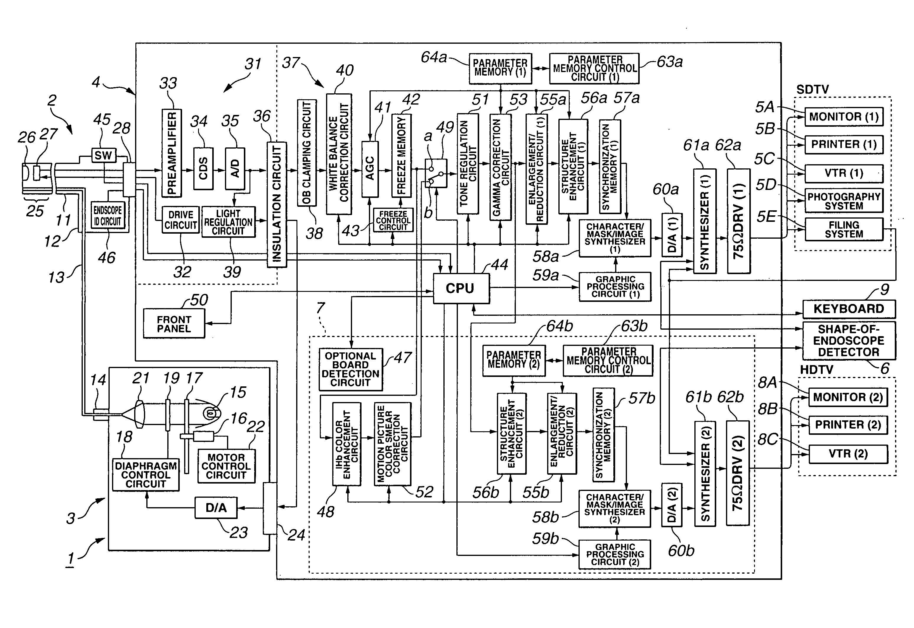
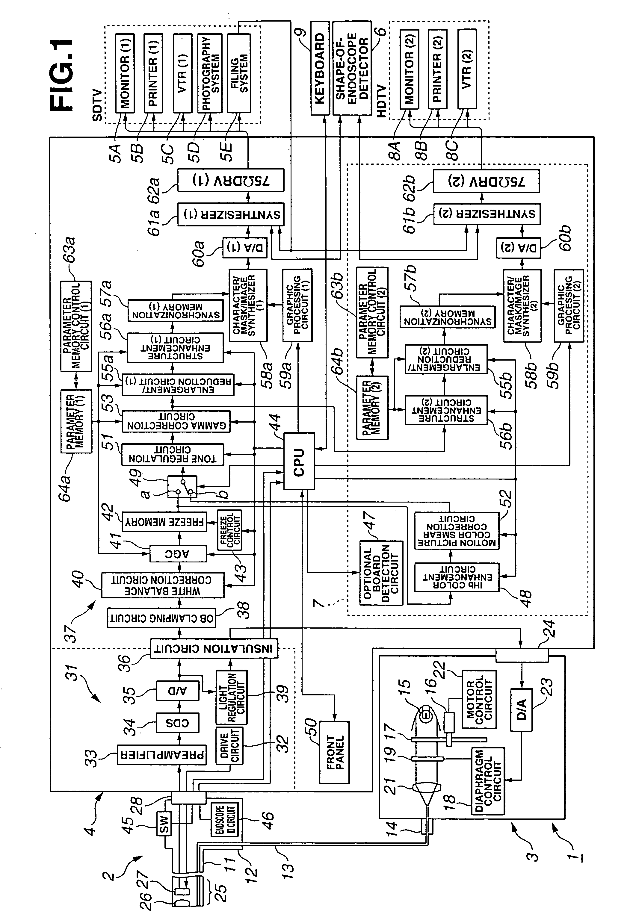
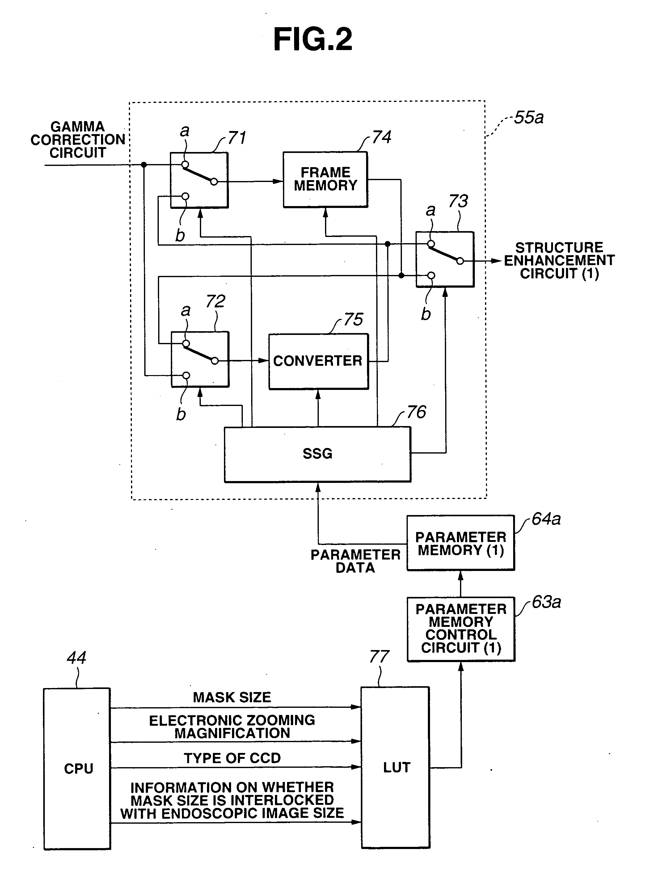
[0027]FIG. 1 to FIG. 13 are concerned with a first embodiment of the present invention. FIG. 1 shows the overall configuration of an electronic endoscope system in accordance with the first embodiment. FIG. 2 shows the circuit elements of an enlargement / reduction circuit. FIG. 3A and FIG. 3B are concrete examples of address data recorded in a lookup table. FIG. 4A, FIG. 4B, and FIG. 4C show concrete examples of a mask size (screen image size) in which an endoscopic image is displayed. FIG. 5A, FIG. 5B, and FIG. 5C show examples of an endoscopic image displayed in a semi-full mask size when enlargement is directed on the condition that an endoscopic image size should not be interlocked with a mask size. FIG. 6 shows an example of a menu screen image that helps a user determine various settings. FIG. 7 shows an example of the layout of components on a front panel. FIG. 8A, FIG. 8B, and FIG. 8C show examples of an endoscopic image displayed when enlargement is ...

second embodiment

[0173] (Second Embodiment)

[0174] Next, a second embodiment of the present invention will be described with reference to FIG. 14, FIG. 15A, and FIG. 15B. FIG. 14 shows the circuit elements mounted on an optional board on which an extension feature is implemented according to the second embodiment.

[0175] According to the first embodiment, a signal processed by the structure enhancement circuit (2) 56b and enlargement / reduction circuit (2) 55b is transferred to the synchronization memory (2) 57b. According to the present embodiment, a high-band correction circuit 91 is mounted on the optional board 7 so that a signal processed by the enlargement / reduction circuit (2) 55b can be transferred to the synchronization memory (2) 57b via the high-band correction circuit 91 that corrects a high frequency band.

[0176] Moreover, the CPU 44 transfers a type of structure enhancement and a level thereof to a structure enhancement circuit (2) lookup table 92. The CPU 44 reads from the structure enh...


PUM


Abstract

A CPU included in a video processor detects the type of CCD incorporated in an electronic endoscope actually connected to the video processor on the basis of identification information sent from an incorporated endoscope identification circuit. Moreover, when an optional board is loaded, an optional board detector detects an extension feature to be implemented on the optional board. For example, when the incorporated CCD offers a small number of pixels, restrictions are imposed for fear an enlargement / reduction circuit may perform enhancement based on electronic zooming. Moreover, an indication that the feature is invalid is established. Thus, a user is prevented from performing unnecessary handling. This results in improved maneuverability.

Description

TECHNICAL FIELD [0001] The present invention relates to an electronic endoscope system in which an endoscopic image produced by an image pick-up means realized with a solid-state imaging device is displayed on a display means. BACKGROUND ART [0002] In recent years, electronic endoscope systems have widely prevailed as a modality that displays on a display device an endoscopic image, which is produced by an image pick-up device realized with a solid-state imaging device and is transmitted to the display device, so as to assist in endoscopic examination or diagnosis. [0003] The electronic endoscope systems include a type of electronic endoscope system that permits use of electronic endoscopes whose solid-state imaging devices offer different numbers of pixels. Moreover, a related art concerning the electronic endoscope system, for example, the one described in Japanese Unexamined Patent Application Publication No. 2000-354240 provides a system including a signal processing unit in whi...

Claims


Application Information

Patent Timeline
IPC IPC(8): A61B1/04G02B23/24A61B1/05H04N5/225H04N5/232
CPCA61B1/00039A61B1/00041A61B1/00059H04N2005/2255A61B1/051H04N5/23209H04N5/335A61B1/05A61B1/0004A61B1/00042H04N23/555H04N23/663H04N25/00
Inventor SUZUKI, TATSUHIKO
Owner OLYMPUS CORP
Learn More