Scroll type compressor

a compressor and roller technology, applied in the direction of machines/engines, rotary/oscillating piston pump components, liquid fuel engines, etc., can solve the problems of high processing precision (machining performance) of the spiral passage, and the difficulty of processing the spiral passage, so as to achieve enhanced finishing precision of the inner peripheral surface of the second path (insertion hole) and high precision

Inactive Publication Date: 2010-08-26
SANYO ELECTRIC CO LTD
View PDF12 Cites 7 Cited by
  • Summary
  • Abstract
  • Description
  • Claims
  • Application Information

AI Technical Summary

Benefits of technology

[0016]Furthermore, the reaming processing is conducted from the one end of the first path till the predetermined depth position of the first path, and thus the finishing precision of the inner peripheral surface of the second path (insertion hole) is enhanced, and the size of the gap between the outer periphery of the pin member and the inner periphery of the intercommunication path and the size of the gap between the outer periphery of the pin member and the low-pressure opening opened to the low pressure portion in the scroll can be ma

Problems solved by technology

In the construction disclosed in the above publication, the restriction of the flow rate is dependent on the size of the spiral passage formed on the outer periphery of the main

Method used


Image

  • Scroll type compressor
  • Scroll type compressor
  • Scroll type compressor

Examples


Embodiment Construction

[0023]A preferred embodiment according to the present invention will be described hereunder with reference to the accompanying drawings.

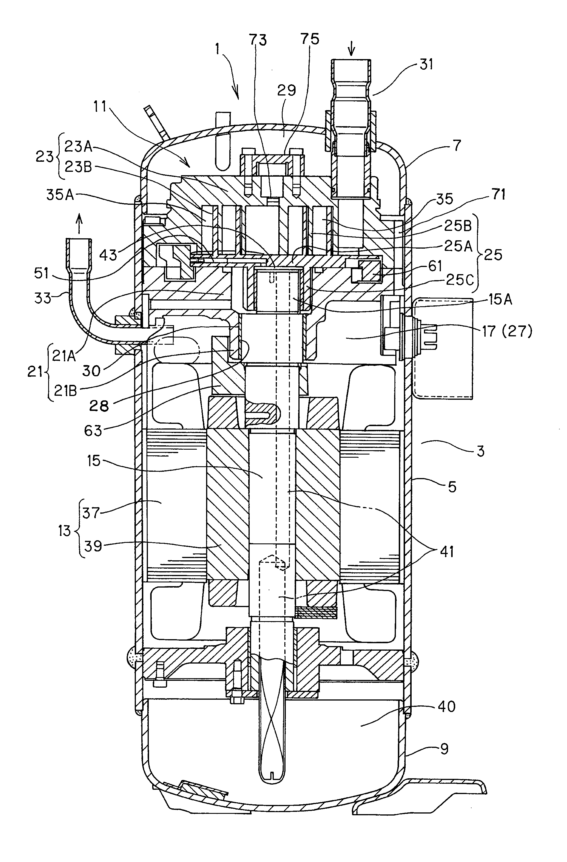
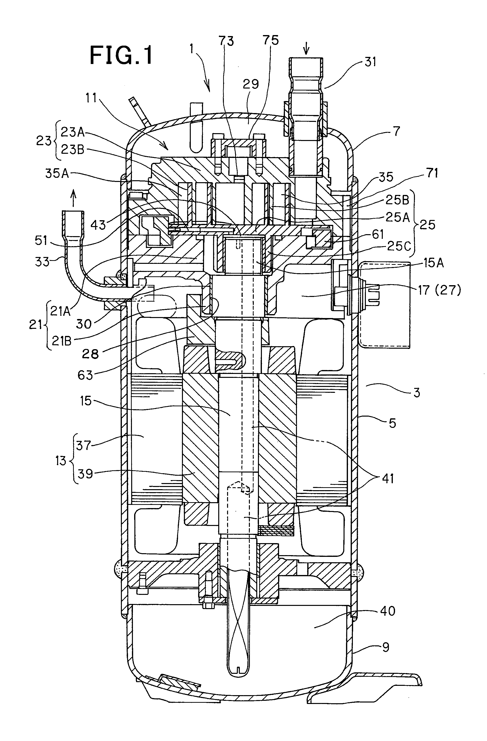
[0024]In FIG. 1, reference numeral 1 represents a scroll type compressor having a high internal pressure. The compressor 1 is connected to a refrigerant circuit (not shown) in which refrigerant is circulated to perform a refrigeration cycle operation, and compresses the refrigerant. The compressor 1 has a hermetically-sealed dome type casing 3 which is designed in an elongated cylindrical shape.

[0025]The casing 3 is constructed as a pressure container by a casing main body 5 as a cylindrical body portion having an axis line in the up-and-down direction, a saucer-shaped upper cap 7 which is air-tightly welded and integrally joined to the upper end portion of the casing main body 5 and has an upwardly projecting convex surface, and a saucer-shaped lower cap 7 having a downwardly projecting convex surface, and the inside of the casing 3 is designed to ...


PUM


Abstract

A scroll type compressor including a fixed scroll, a movable scroll engaged with the fixed scroll, and a hermetically sealed container in which the fixed scroll and the movable scroll are mounted. The fixed scroll or the movable scroll has an intercommunication path for lubricating oil that is opened to the outside of the one scroll at one end thereof, extends radially inside the scroll and has a high-pressure opening intercommunicating with a high-pressure portion of the container and a low-pressure opening intercommunicating with a low-pressure portion in the scroll, a pin member disposed in the intercommunication path so as to be movable radially in the scroll, a screw member closing one end of the intercommunication path, and a stopper provided at a predetermined position in the intercommunication path to regulate radial movement of the pin member.

Description

INCORPORATION BY REFERENCE[0001]The present application claims priority under 35 U.S.C. §119 to Japanese Patent Application No. 2009-037444 filed on Feb. 20, 2009. The content of the application is incorporated herein by reference in its entirety.BACKGROUND OF THE INVENTION[0002]1. Field of the Invention[0003]The present invention relates to a scroll type compressor having an oil path through which lubricating oil is supplied to engagement portions at a low-pressure side between a fixed scroll and a movable scroll.[0004]2. Description of the Related Art[0005]There is known a scroll type compressor in which a fixed scroll and a movable scroll engaged with the fixed scroll are accommodated in a hermetically sealed container. In this type of scroll compressors, there has been proposed a scroll type compressor which has an oil path for supplying lubricating oil to an engagement portion at the low-pressure side between the fixed scroll and the movable scroll, and a flow rate restricting ...

Claims


Application Information

Patent Timeline
IPC IPC(8): F04C29/02F04C18/02
CPCF04C18/0215F04C29/028F04C23/008F04C18/0253F04C18/02F04C18/356
Inventor KIYOKAWA, YASUNORIKOIKE, YOSHIAKIKON, TSUTOMUAKUZAWA, KATSUKIIITSUKA, SATOSHIAIDA, KENJIHAYASHI, AKIHIROSUGIMOTO, KAZUYOSHI
Owner SANYO ELECTRIC CO LTD
Why Eureka
Try Eureka