Porous glass fused onto stent for drug retention

a technology of porous glass and stent, which is applied in the field of porous glass fused onto stent for drug retention, can solve the problems of polymer cracking in subsequent processing steps, excessive material, and often adverse or even toxic side effects of systemic dosing

Inactive Publication Date: 2005-01-27
ABBOTT CARDIOVASCULAR
View PDF99 Cites 149 Cited by
  • Summary
  • Abstract
  • Description
  • Claims
  • Application Information

AI Technical Summary

Benefits of technology

This patent describes a new type of medical device that can be placed inside a person's body. Its special part made from ceramic has tiny holes all over it, with different levels of thickness. There may also be something called an oxide layer which helps hold everything together.

Problems solved by technology

The technical problem addressed in this patent text relates to finding methods of increased drug concentration within stents while avoiding an increase in the amount of polymer binder needed to carry the drugs. Excessive materials may lead to cracks during processing and potential negative biological impacts.

Method used


Image

  • Porous glass fused onto stent for drug retention
  • Porous glass fused onto stent for drug retention
  • Porous glass fused onto stent for drug retention

Examples


Embodiment Construction

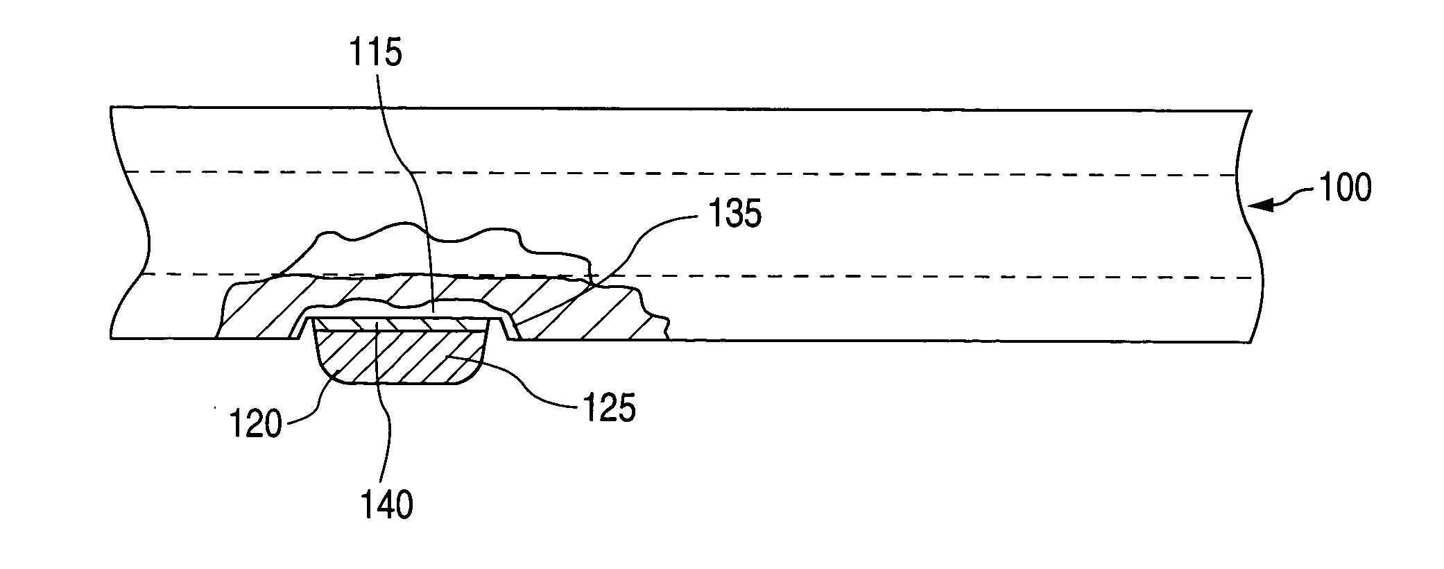
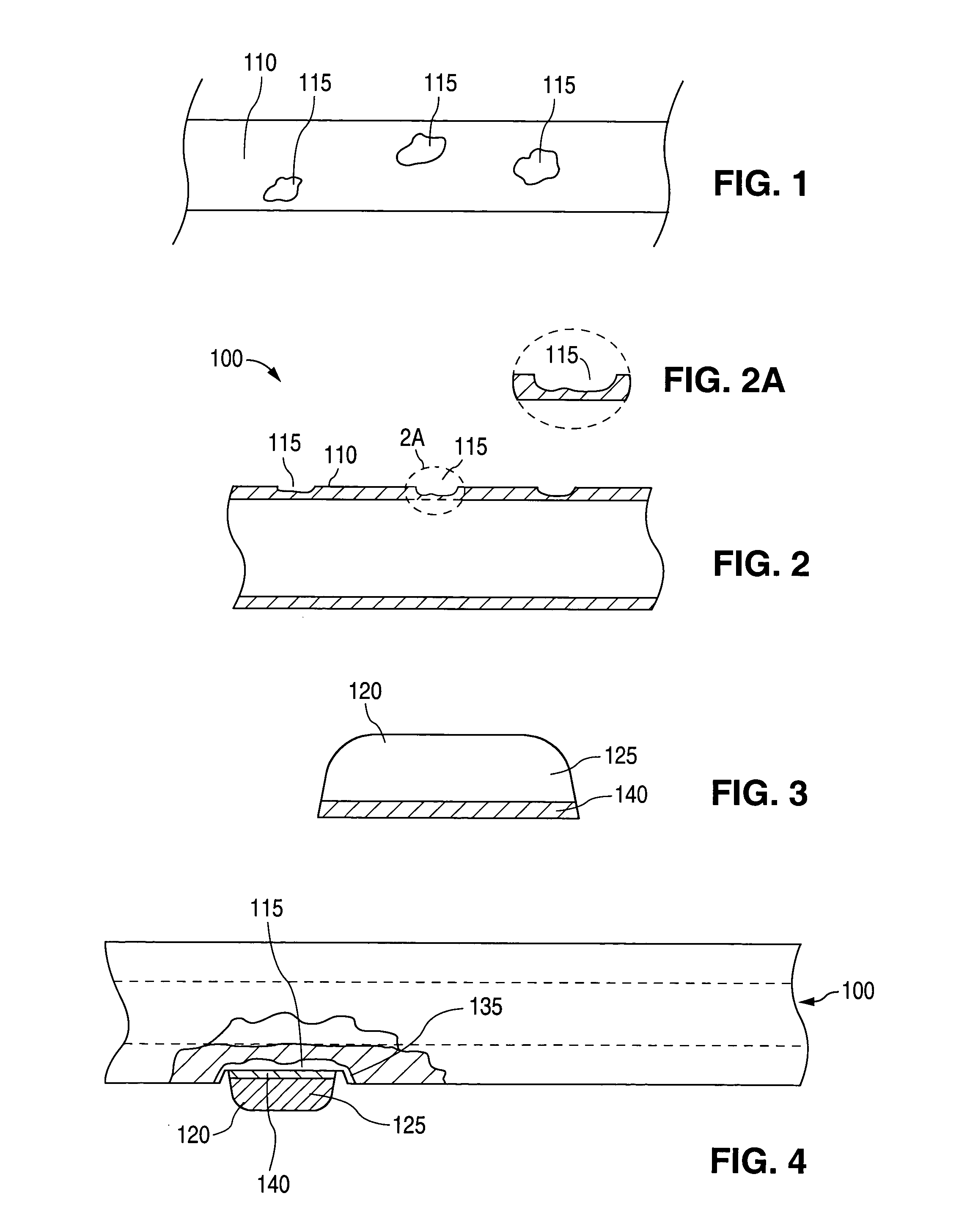
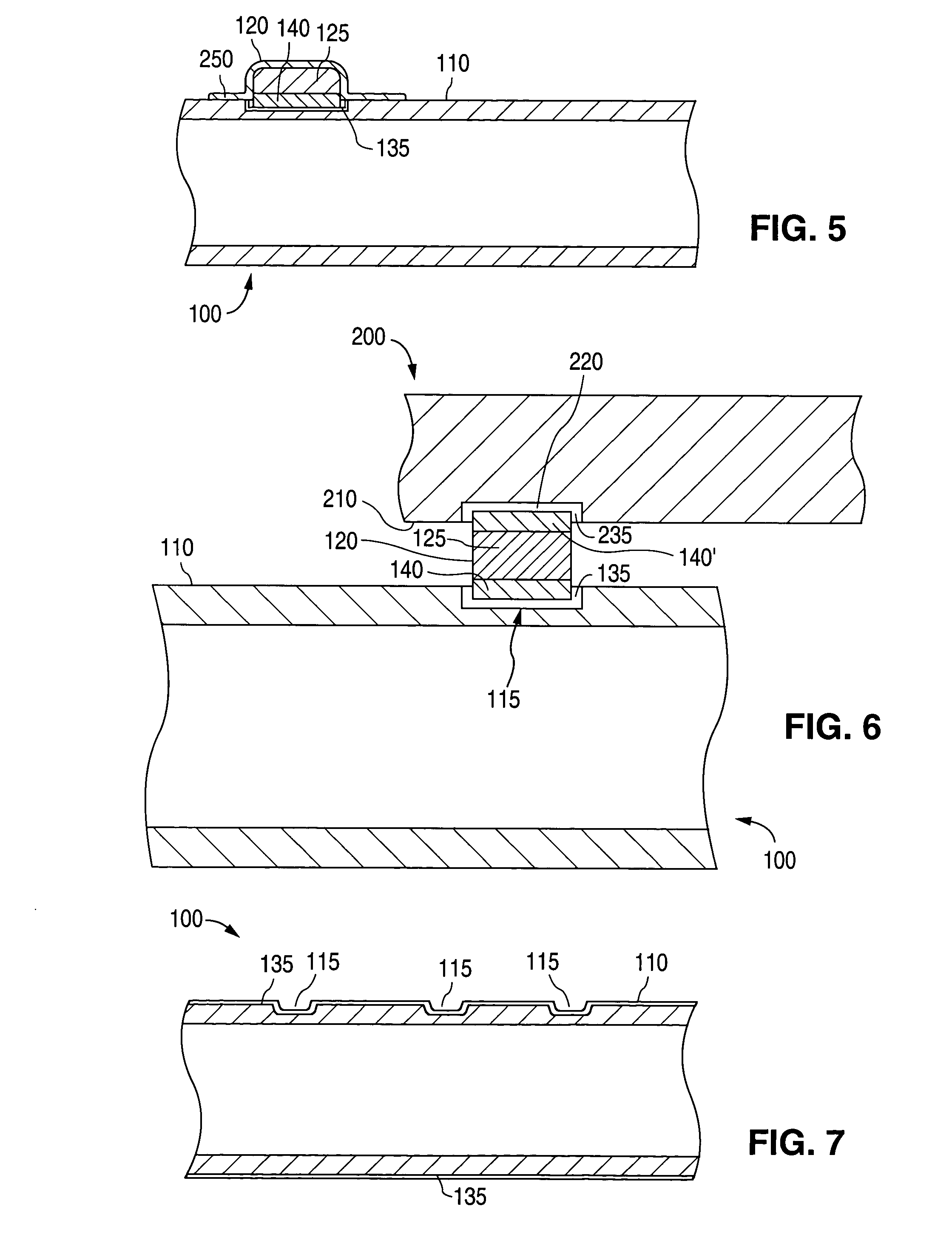
[0019] As can be seen by reference to FIGS. 1 and 2, the implantable medical device 100 comprises a surface 110 with at least one attachment region 115 to which a glass or ceramic component 120 attaches. (FIG. 3) The term “ceramic component” encompasses components comprising ceramic or glass unless otherwise indicated.

[0020] When the ceramic component 120 attaches to the surface 110, the attachment region 115 is a portion of the surface 110. Alternatively, an attachment region is formed in the surface 110 by removing material. In those cases, the attachment region 115 is the surface left behind after the material has been removed. Attachment regions 115 are formed in any material to which the ceramic component 120 can attach using one of the attachment methods described below. In some embodiments, attachment regions 115 are formed in surfaces 110 that are metal. In some of these embodiments, the metal is selected from stainless steel, tantalum, niobium, super-elastic nickel-titaniu...


PUM


Abstract

An implantable medical device that comprises an attached porous ceramic component is disclosed. This ceramic component joins the surface of the medical device to an auxiliary component such as a glass, plastic, ceramic, or metal device. This auxiliary component can be fiber optic, can be an electrode, or can be a sensor or chip-based sensor. Alternatively, the ceramic component is a drug reservoir capable of locally delivering a drug or other therapeutic substance near the implantation site of the medical device.

Description


Claims


Application Information

Patent Timeline
Owner ABBOTT CARDIOVASCULAR
Why Eureka
Try Eureka