Impact wrench having an improved anvil to square driver transition

a technology of impact wrench and square driver, which is applied in the direction of wrenches, power driven tools, screwdrivers, etc., can solve the problems of loose fit to the square portion of the anvil, increased stress, and inefficiencies in design

Inactive Publication Date: 2005-02-03
BLACK & DECKER INC
View PDF15 Cites 12 Cited by
  • Summary
  • Abstract
  • Description
  • Claims
  • Application Information

AI Technical Summary

Problems solved by technology

These sharp radii may create some inefficiencies in the design.
However, the impact socket may, over a long period of use, become “damaged”, resulting in a looser fit to the square portion of the anvil.
These points of contact form at the sharp radii in the transition between the round body and the square drive and lead to points of increased stress.
Moreover, as the impact socket becomes “damaged”, the corners of the impact socket tend to “dig” into the sharp radii in the transition.
This digging between the impact socket and the square portion can damage the anvil.
As the stress builds at these points, the anvil may fail at the sharp radii.
This then can contribute to an early failure of the anvil.
However, this added step increases the overall cost of manufacturing the anvil and does not directly address the problems associated with the sharp radii.

Method used


Image

  • Impact wrench having an improved anvil to square driver transition
  • Impact wrench having an improved anvil to square driver transition
  • Impact wrench having an improved anvil to square driver transition

Examples


Embodiment Construction

[0017] The following description of the preferred embodiment is merely exemplary in nature and is in no way intended to limit the invention, its application, or uses.

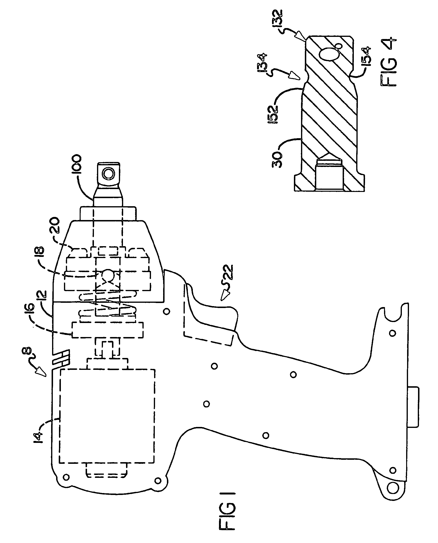
[0018] With reference to FIG. 1 of the drawings, an exemplary impact wrench 8 is illustrated to include an improved anvil 100 that is constructed in accordance with the teachings of the present invention. The impact wrench 8 also includes a housing 12 containing an electric motor 14 whose output is coupled to a gear assembly 16. The gear assembly 16 transfers the output to a cam and carrier 18 which in turn drives an impactor 20. The improved anvil 100 is mounted within the impactor 20. A trigger and handle assembly 22 mounted to the housing 12 is used to activate the electric motor 14.

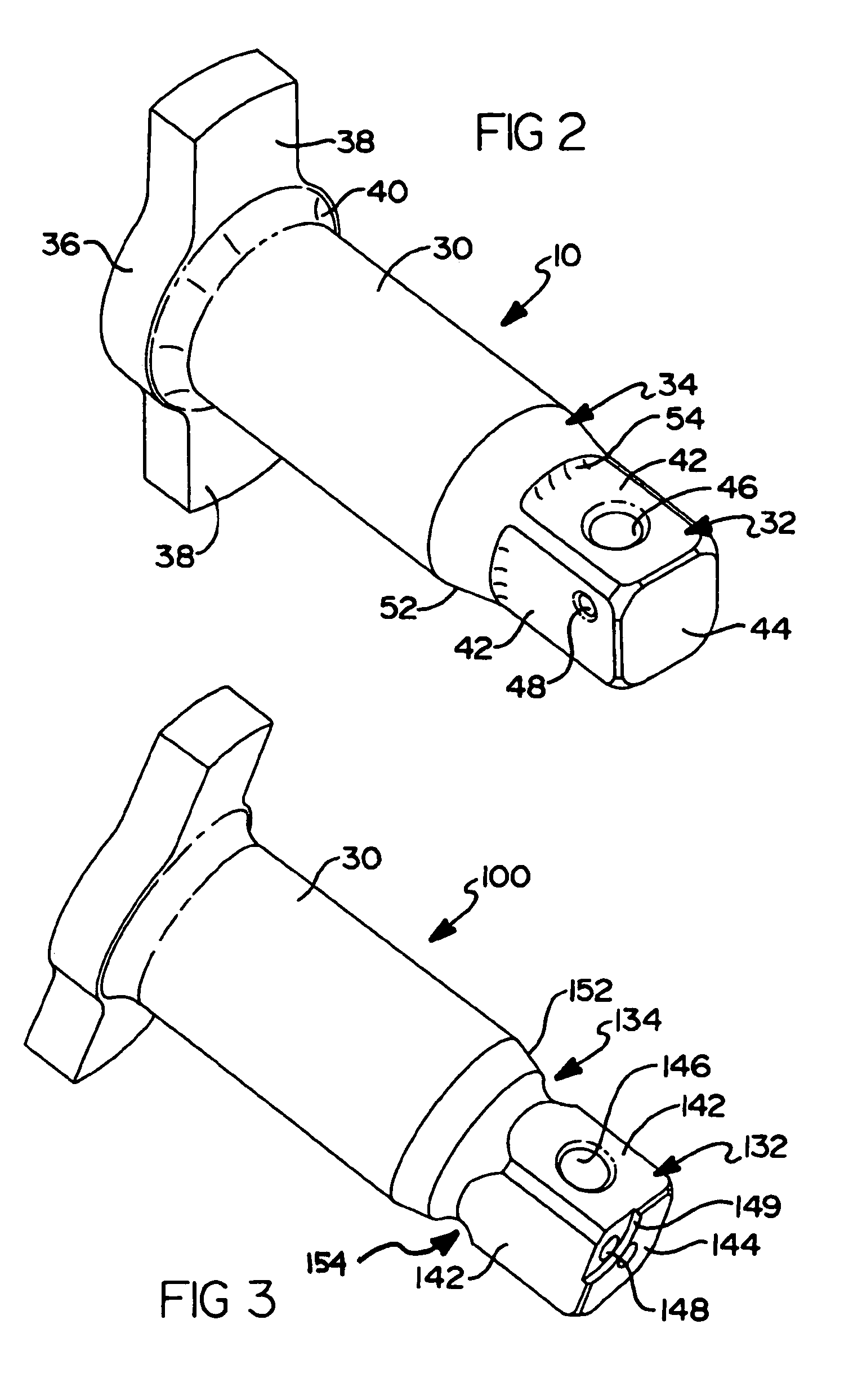
[0019] With reference now to FIG. 2, a prior art anvil is indicated by reference numeral 10. The prior art anvil 10 includes a round body 30 and a square drive head 32. A transition zone 34 connects the round body 30 to the square drive...


PUM


Abstract

An anvil adapted to be received within an impact wrench comprises a round body and a square head. The square head is formed at an end of the round body. A tapered ramp extends from the round body to the square head. A radius is formed in the tapered ramp. The radius is defined by a removal of material in the tapered ramp.

Description

CROSS-REFERENCE TO RELATED APPLICATIONS [0001] This application is a continuation-in-part of U.S. patent application Ser. No. 10 / 630,263 filed on Jul. 30, 2003. The disclosure of the above application is incorporated herein by reference.FIELD OF THE INVENTION [0002] The present invention relates to an impact wrench and more particularly to an improved anvil in an impact wrench. BACKGROUND OF THE INVENTION [0003] The traditional design of an anvil for use in an impact wrench includes a round portion that transitions to a square portion. The round portion is received within the impact wrench and acts as a bearing journal. The square portion is received within an impact socket. The transition from the round cross section to the square cross section inherently creates sharp radii within the transition. [0004] These sharp radii may create some inefficiencies in the design. Initially there is minimal clearance between the square portion of the anvil and the impact socket when the pieces a...

Claims


Application Information

Patent Timeline
Patent Type & Authority Applications(United States)
IPC IPC(8): B25B15/00B25B21/02B25B23/00
CPCB25B15/001B25B23/0035B25B21/02B25B21/026
Inventor MILBOURNE, RODNEYDEBELIUS, STEPHENKIVETT, BEVERLY
Owner BLACK & DECKER INC
Why Eureka
Try Eureka