Pressurized direct contact heat exchange process

a heat exchange process and pressurized technology, applied in heat exchange apparatus, heat transfer modification, steam engine plants, etc., can solve the problems of low thermal efficiency and large energy loss, and achieve the effect of approving 90% of the thermal efficiency of the process and much higher thermal efficiency

Inactive Publication Date: 2005-02-03
HELLEUR DONALD
View PDF0 Cites 11 Cited by
  • Summary
  • Abstract
  • Description
  • Claims
  • Application Information

AI Technical Summary

Benefits of technology

[0004] A main objective of the present invention is to retain this water within the process and convert it to steam in a more reusable form, and thereby raise the thermal efficiency to a much higher level. This objective is attained by an application of Henry's Law of partial pressures. For example, if the pressure of the gases leaving a pr...

Problems solved by technology

Present industrial processes release large volumes of hot non-condensable gases containing water vapor into the atmosphere resulting in a great loss of en...

Method used


Image

  • Pressurized direct contact heat exchange process
  • Pressurized direct contact heat exchange process
  • Pressurized direct contact heat exchange process

Examples


Embodiment Construction

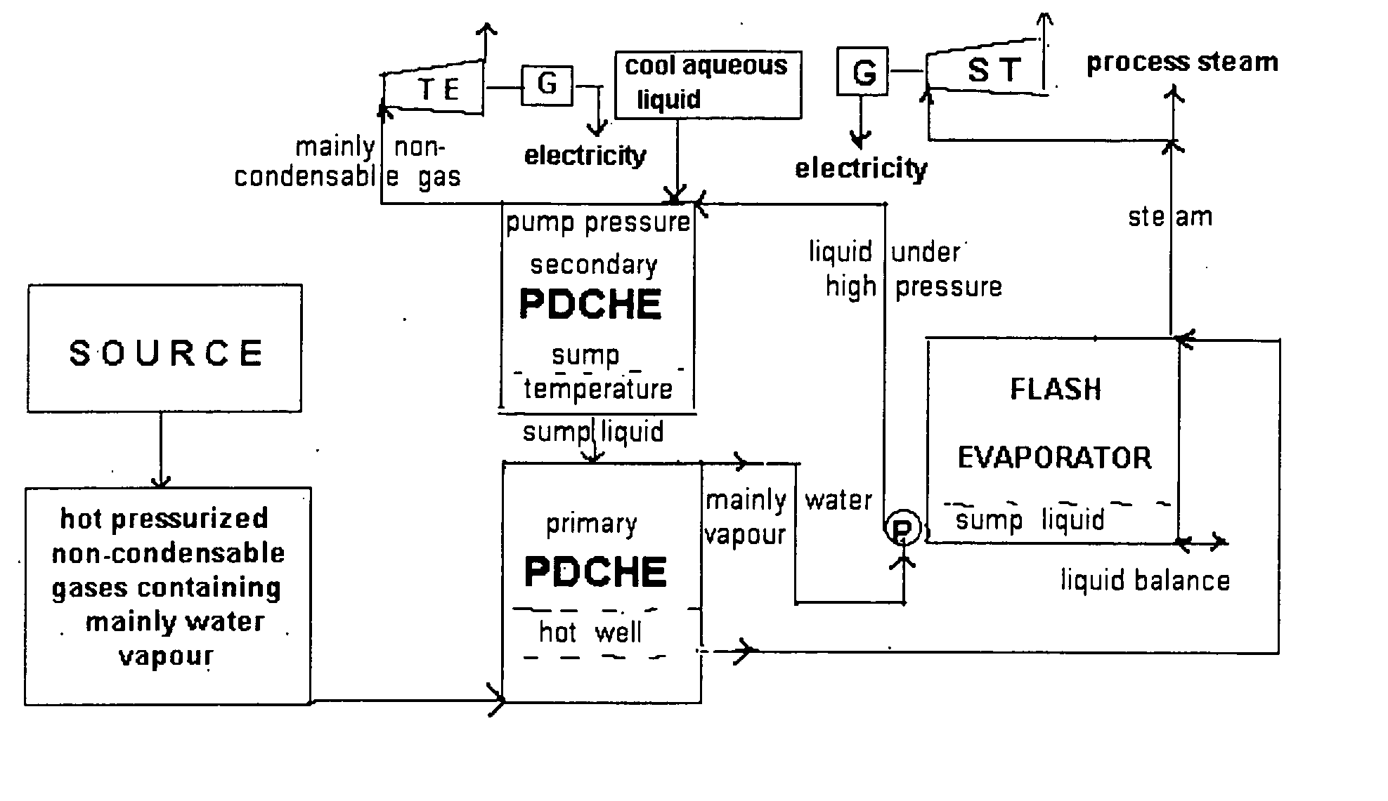
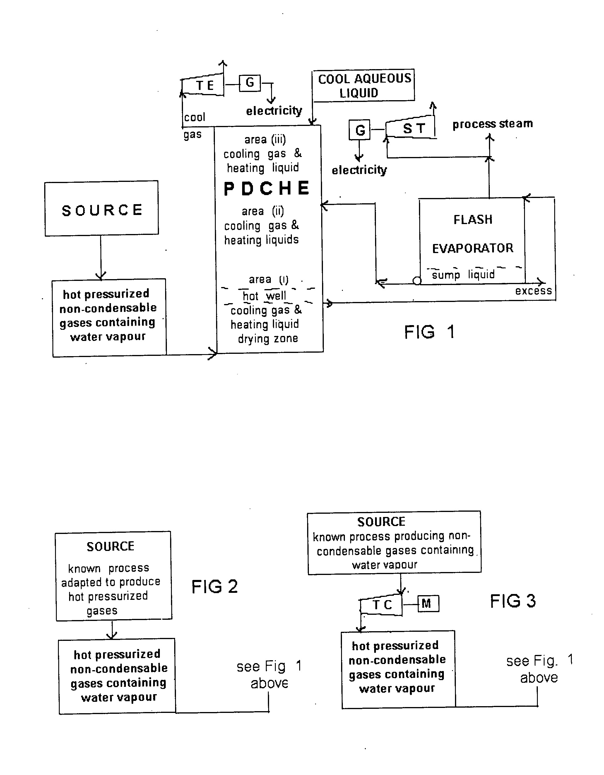
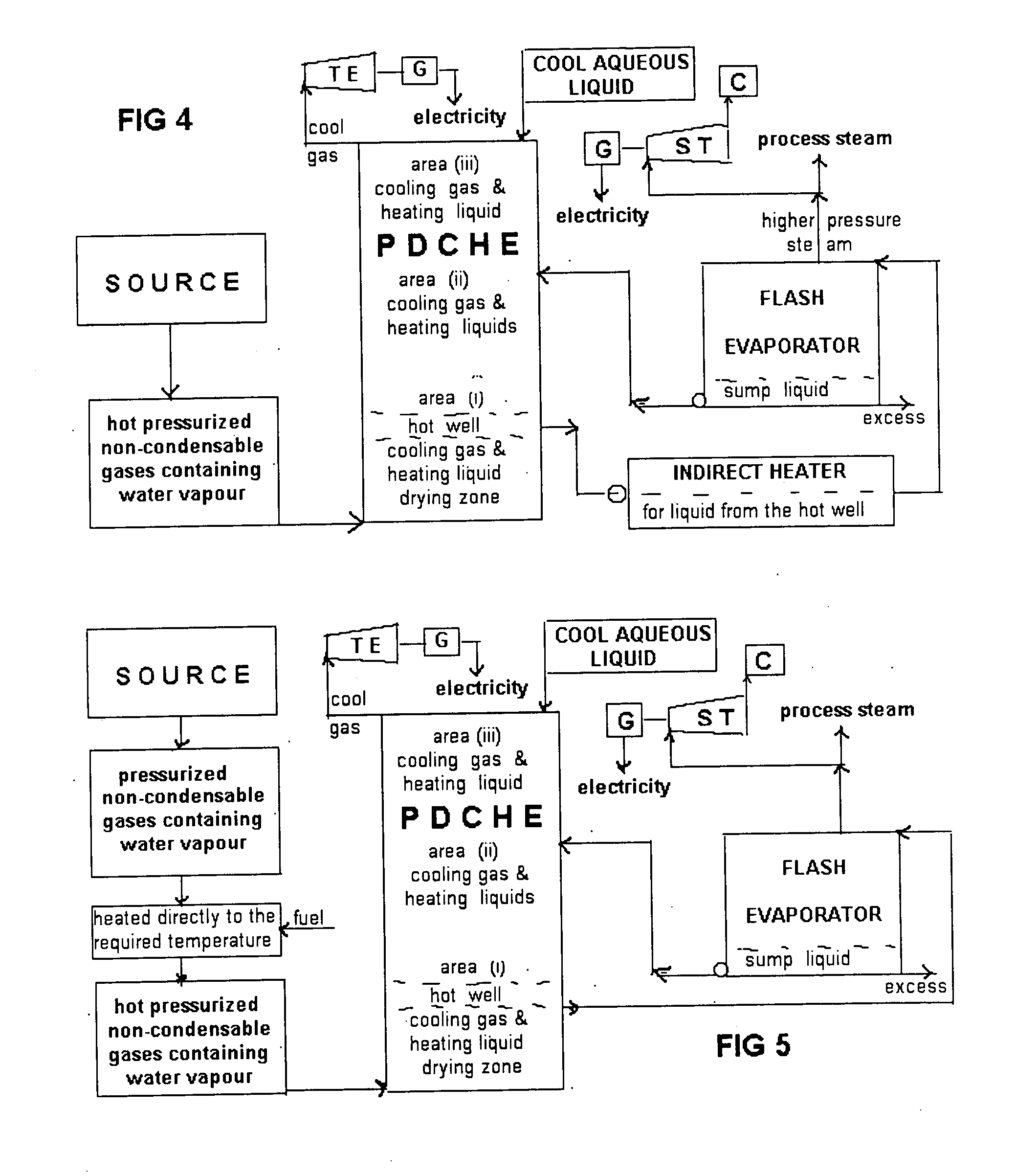
[0028] The following embodiments are process sequences that provide a wide range of choice to fit a wide variety of circumstances, applications and available technologies. Because of the wide range of process variables involved and technologies to choose from it is understood that in most cases, computer simulation would normally be utilized to balance the various variables such as the rate of: recirculation of the hot well liquid; cool liquid supply and excess liquid removal.

[0029] The embodiments as illustrated and described is such as to obtain maximum thermal efficiency, noting that, the higher the pressure and the lower the temperature of the gas leaving the pressurized direct contact heat exchanger the higher the thermal efficiency Embodiments involving lower efficiencies are also included.

[0030] Referring to the accompaning drawings, the symbols used have the following meaning:

GGenerator for electricityGTGas TurbineTCTurbine CompressorTETurbine ExpanderPRParticulate Remov...


PUM


Abstract

A process for converting latent heat of water vapor, appearing with non-condensable gases expelled into the atmosphere, into more useful forms of energy, such as process steam/electricity. It uses pressurized direct contact heat exchange systems to achieve this conversion at high thermal efficiencies. When pressure combustion is used in combination with pressurized water electrolysis it produces pressurized by-product hydrogen which can be used to extract methane from methane hydrate ice located below the earth and sea.

Description

FIELD OF THE INVENTION [0001] This invention relates to sources, which continuously produce hot pressurized non-condensable gases containing water vapor, and which in combination with a pressurized direct contact heat exchange (Pressurized direct contact heat exchanger) process, continuously convert the energy in these gases into a more useful form, such as steam / electricity. DESCRIPTION OF THE PRIOR ART [0002] U.S. Pat. Nos. 3,920,505 and 4,079,585 are previous disclosures relating to heat exchange processes. [0003] Present industrial processes release large volumes of hot non-condensable gases containing water vapor into the atmosphere resulting in a great loss of energy, especially the latent energy of the water vapor. In the case of the combustion of water laden materials or wastes, this results in low thermal efficiencies. SUMMARY OF THE INVENTION [0004] A main objective of the present invention is to retain this water within the process and convert it to steam in a more reusab...

Claims


Application Information

Patent Timeline
IPC IPC(8): F01K3/18
CPCF01K3/185
Inventor HELLEUR, DONALD
Owner HELLEUR DONALD
Why Eureka
Try Eureka