

Peripheral device
a technology of peripheral devices and drivers, which is applied in the direction of input/output to record carriers, instruments, computing, etc., can solve the problems of user trouble when installing such a special driver software program on the personal computer, and achieve the effects of simple configuration, improved user-friendliness, and low cos
- Summary
- Abstract
- Description
- Claims
- Application Information
AI Technical Summary
Benefits of technology
Problems solved by technology
Method used
Image

Examples
first embodiment
[0099] First, a multifunction device 1 will be described with reference to FIGS. 1-10.
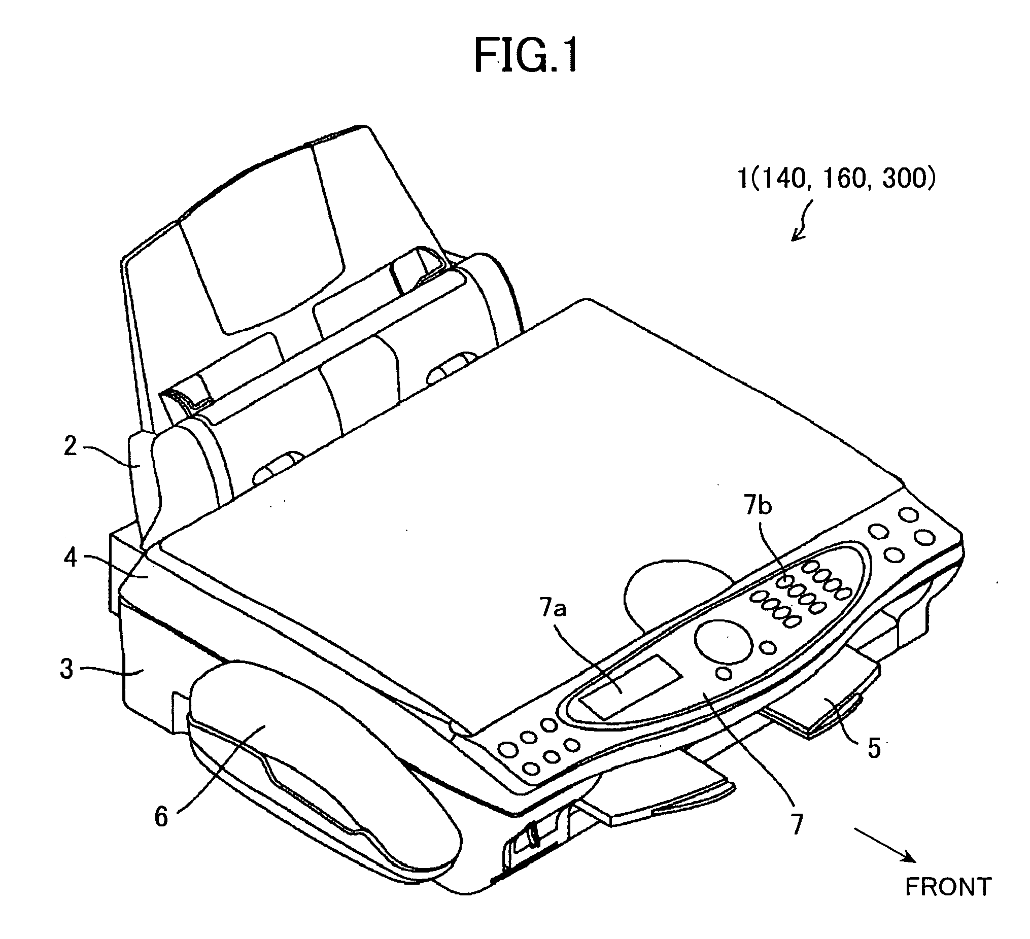
[0100] First, the overall configuration of a multifunction device 1 of the first embodiment of the present invention will be described with reference to FIG. 1 and FIG. 2. The multifunction device is provided with a printer function, copy function, scanner function, facsimile function, and telephone function.
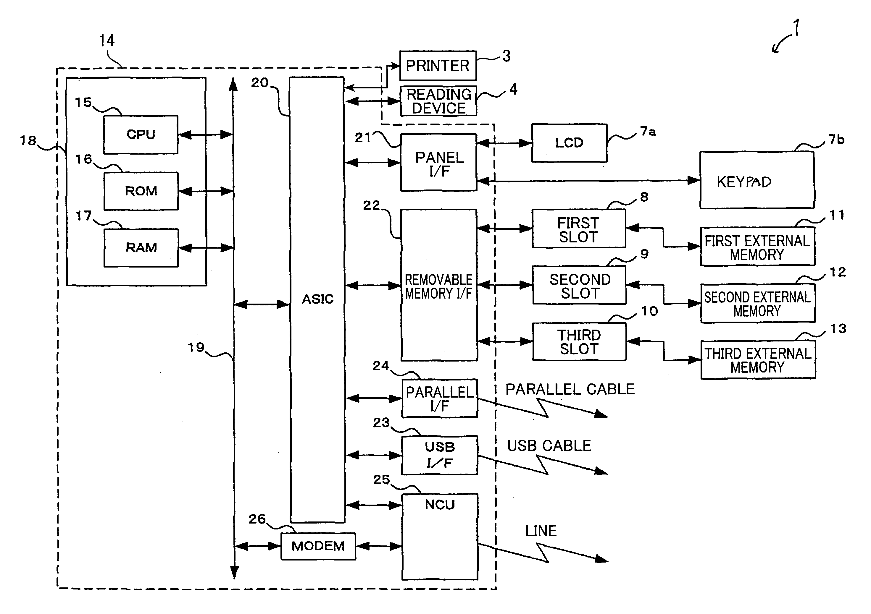
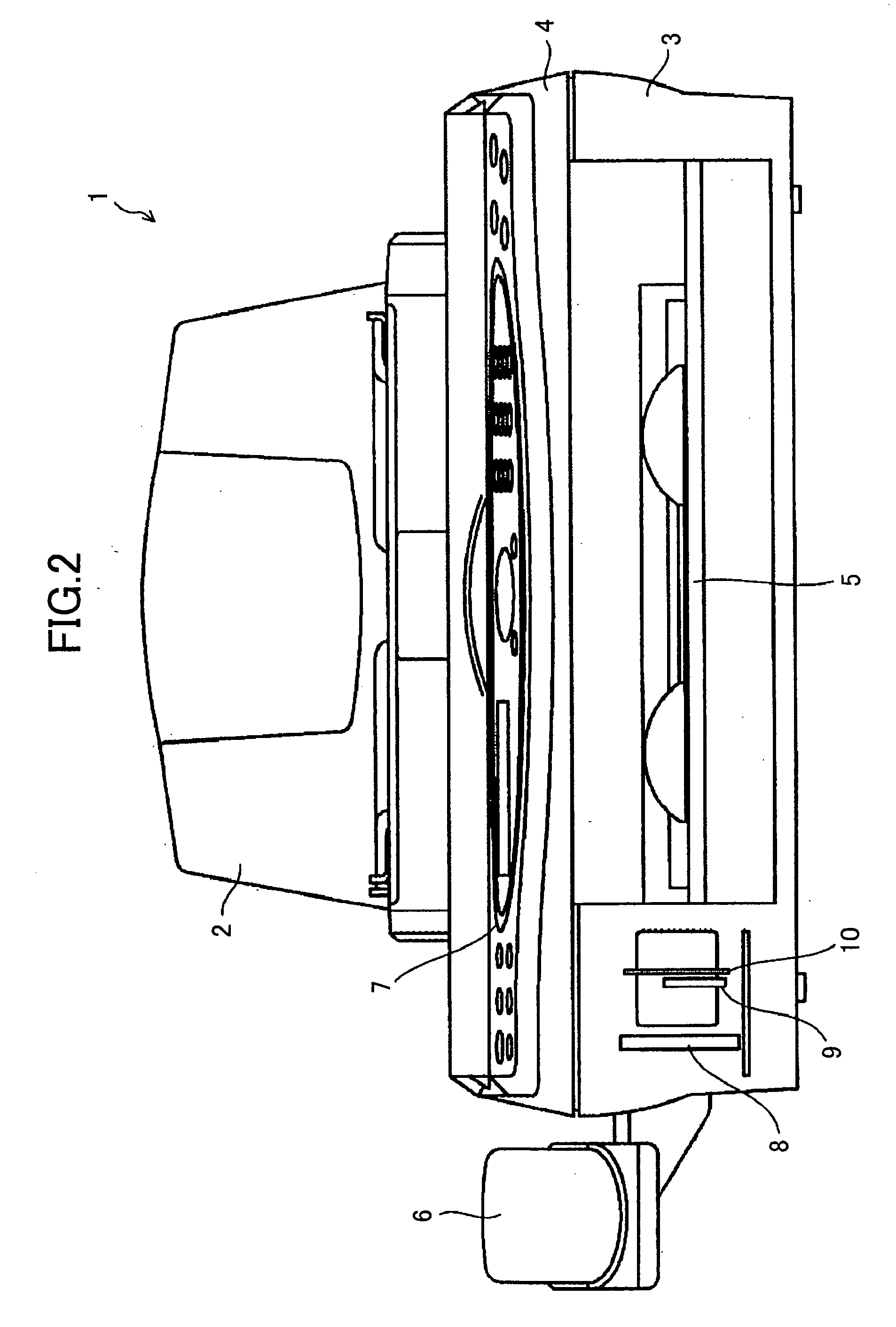
[0101] The multifunction device 1 has a paper feed device 2 located at its rear, an inkjet printer 3 located on a front side of the lower part of the paper feed device 2, a reading device 4 for a copy function and facsimile function located above the printer 3, a paper discharge tray 5 located on a front side of the printer 3, a telephone 6 located on the left of the reading device 4, and a control panel 7 located on the front top part of the reading device 4. The control panel 7 has an LCD 7a and a keypad 7b.
[0102] To the left of paper discharge tray 5, the multifunction device 1 has a firs...
second embodiment
[0161] Next, a multifunction device 1′ will be described with reference to FIG. 10(a).
[0162] As shown in FIG. 10(a), the multifunction device 1′ is the same as the multifunction device 1 of the first embodiment except that the multifunction device 1′ is provided with an internal memory 27. The multifunction device 1′ executes the drive mode setting process in the same manner as in FIG. 4.
[0163] In this example, the internal memory 27 is configured of an independent internal memory, which is connected to the ASIC 20. Representative examples of the independent internal memory include: a hard disk, a RAM (random access memory), and a fixed flash memory, which is not of a card-type but is directly soldered to the ASIC 20. It is noted, however, that a part of the memory area in the RAM 17 may be utilized as the internal memory 27.
[0164] According to the present embodiment, in the single drive mode (S41 in FIG. 4), when media is not inserted in any of the first slot 8, second slot 9, o...
third embodiment
[0179] Thus, it is possible to allow the user to manipulate the access selection switch 7c, in the single drive mode, to select either: the media first-insertion slot among the slots 8, 9, and 10; or the internal memory 27 to be accessible by the personal computer.
[0180]
[0181] Furthermore, the multifunction devices 1 and 1′ of the first through third embodiments may be applied to a card reader. In this case, when the card reader is connected to a personal computer via a USB cable, the entire card reader becomes a “storage class” device as shown in FIG. 11.
[0182]
PUM
 Abstract
Description
Claims
Application Information