Multipurpose airfoil assembly

a multi-purpose, airfoil technology, applied in the field of airfoils, can solve the problems of reducing airspeed, limiting the ability of the wing to sustain flight in higher angles of attack, and not having aerodynamically enhancing lift attributes configured,

Inactive Publication Date: 2005-02-03
PINCHEFSKY BARRY
View PDF27 Cites 0 Cited by
  • Summary
  • Abstract
  • Description
  • Claims
  • Application Information

AI Technical Summary

Benefits of technology

[0012] A multipurpose airfoil assembly is provided comprising a body, at least one pair of wings, and control system. The body and wings defining a leaf shaped airfoil. The body has a first end and a second end, a structure, and a skin. The first end and the second end define a longitudinal axis. The structure has at least one member aligned to the longitudinal axis. The wings include a wing structure and a wing airfoil with one of the pairs of wings having a forward swept leading edge and a forward swept trailing edge. The control system is configured for controlling the directional movement of the airfoil assembly. The control system suitably connects the airfoil assembly with a person for directional control.

Problems solved by technology

Each of these kites, however, are limited by their configuration and don not have aerodynamically enhancing lift attributes configured to support flight and / or maneuverability in the light wind conditions that frequently occur with kites.
The wing has a traditional aft swept configuration, however, which is limited in its ability to sustain flight in higher angles of attack and at reduced airspeeds.
Both of these innovations focus on enhancing the air captured by the opened parachute, however, both Volf and Ferguson lack the flexibility that can be imparted by a parachute having lift enhancing shapes.
Neither of these patents, however, addresses the ability of a sail to enhance performance under light wind.

Method used


Image

  • Multipurpose airfoil assembly
  • Multipurpose airfoil assembly
  • Multipurpose airfoil assembly

Examples


Embodiment Construction

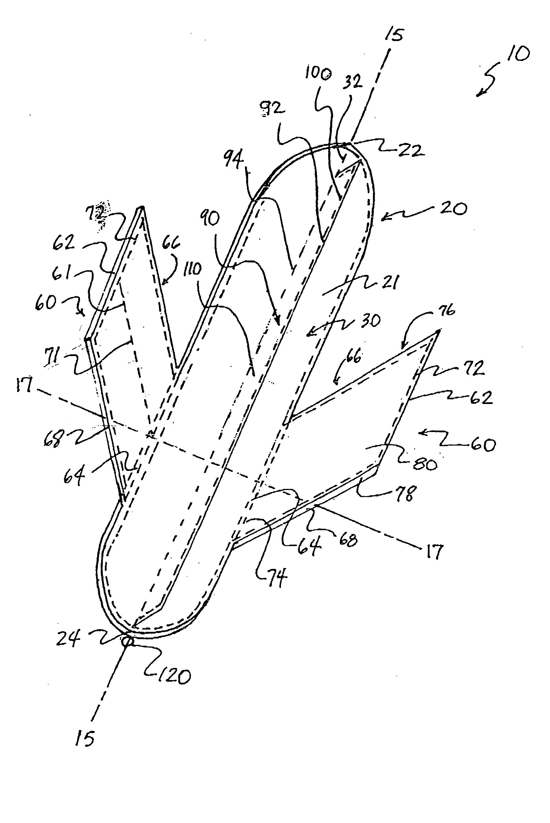
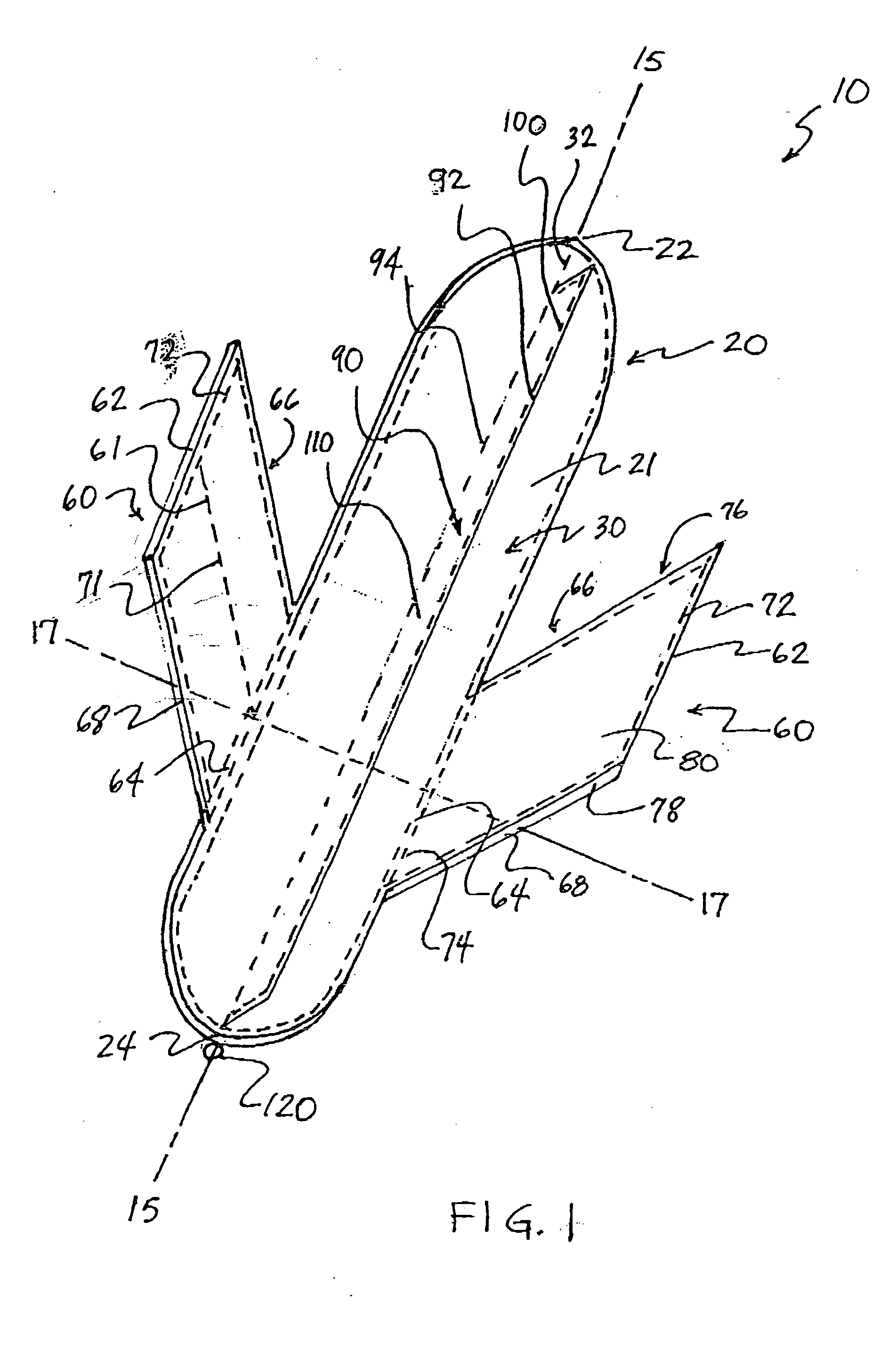
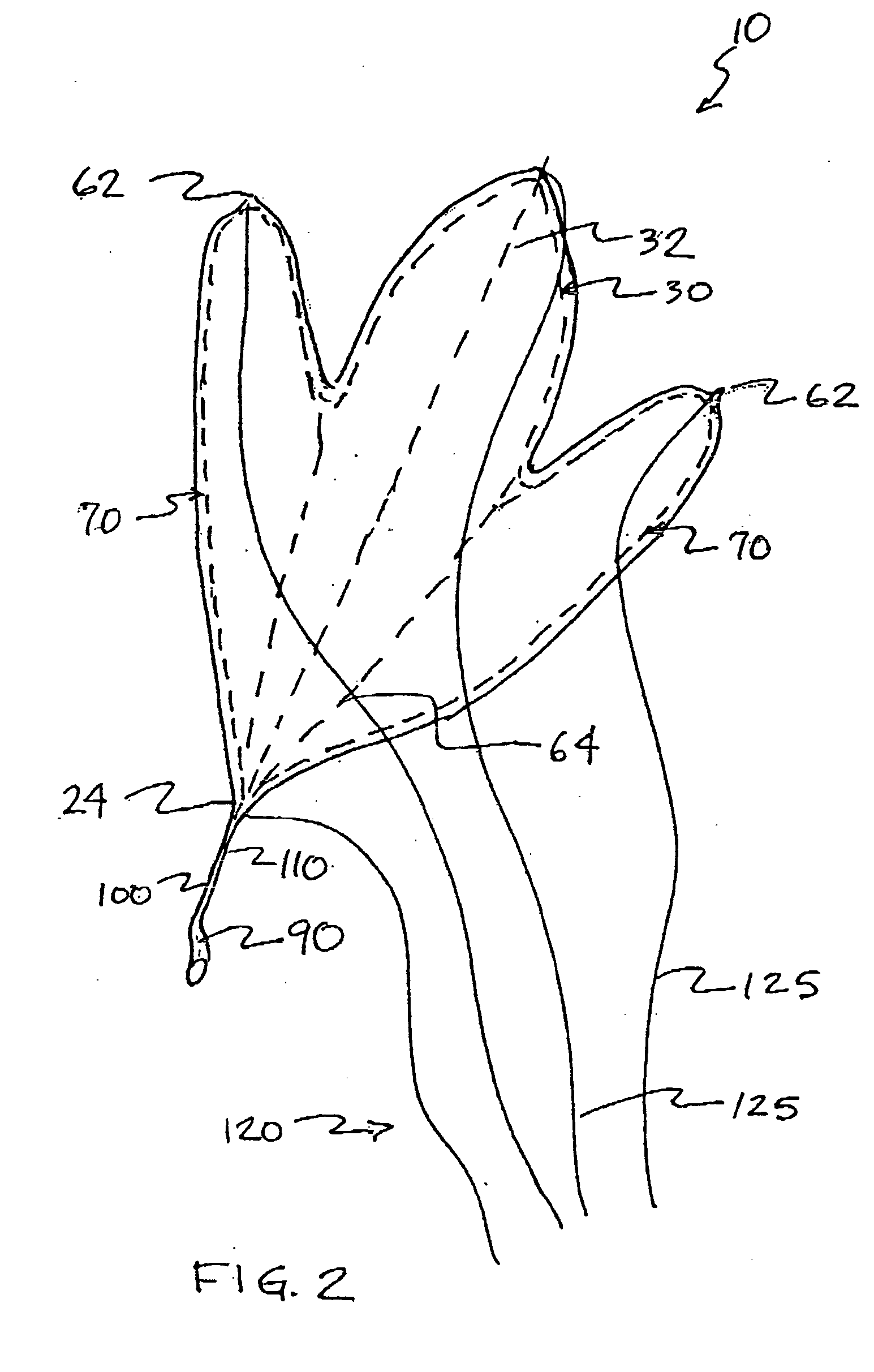
[0022] Referring now in specific detail to the drawings in which like referenced numerals identify similar or identical elements throughout the several view, and initially to FIG. 1, a novel airfoil assembly 10 having a body 20, wings 60, and a control system 120 is shown constructed in accordance with the present disclosure.

[0023] Body 20 has a first end 22 and a second end 24. First end 22 and second end 24 define a first longitudinal axis 15 and a second longitudinal axis 17 perpendicular to first longitudinal axis 15. The intersection of first axis 15 and second axis 17 defines a first plane. Second end 24 is directionally defined as aft and first end 22 is directionally defined as forward, as commonly used in aeronautical terms. Body 20 has a first side 21, preferably oriented into the relative wind, and an opposing second side (not shown). Body 20 includes a structure 30 and an airfoil or skin 40. Structure 30 has a member 32 defining a centerline of body 20. Member 32 and ad...


PUM


Abstract

The present disclosure describes a multipurpose airfoil assembly including a body, at least one pair of wings, and a control system. The body provides a structural connection for the wings. At least one of the pairs of wings has forward swept leading edges and forward swept trailing edges. The shape of the airfoil assembly can range from that of a traditional airframe to a natural leaf like structure. The airfoil assembly can also include a rudder. A control system is provided for directionally controlling the airfoil assembly during its operation. The airfoil assembly can be readily adapted to configurations suitable for a kite, a hang glider, a parachute, and a sail.

Description

BACKGROUND [0001] 1. Technical Field [0002] The present disclosure relates to airfoils having application in multiple lifting apparatuses. More particularly, the present disclosure relates to airfoil assemblies having wing shapes providing advantageous aerodynamic attributes. [0003] 2. Background of Related Art [0004] Airfoils have a broad spectrum of shapes tailored for their specific applications. As one example, a kite typically has a thin lightweight fabric airfoil stretched tightly between structural members. A parachute, in contrast is light weight, but is packaged for rapid expansion and has the strength to safely decelerate a decent. The stresses a sail undergoes during its use are similarly distinct. While many modem sails are fabricated of man made light weight materials such as nylon and composites, sails are often still made of durable sail cloth. In each application, the material of the airfoil requires suitable strength environmental endurance, and support from a struc...

Claims


Application Information

Patent Timeline
Patent Type & Authority Applications(United States)
IPC IPC(8): A63H27/08
CPCA63H27/08B63H9/04
Inventor PINCHEFSKY, BARRY
Owner PINCHEFSKY BARRY
Why Eureka
Try Eureka