Vehicle body structure

Inactive Publication Date: 2005-02-03
NISSAN MOTOR CO LTD
View PDF16 Cites 46 Cited by
  • Summary
  • Abstract
  • Description
  • Claims
  • Application Information

AI Technical Summary

Benefits of technology

[0010] Moreover, demand has increased in recent years for more convenience due to diversification in the size and shape of vehicles. Accordingly, comprehensive improvements need to be made for controlling the mode of the inward movement of center pillar and increasing the strength of the vehicle body.
[0011] In view of this, the

Problems solved by technology

It has been discovered that in such a conventional lateral surface structure of a vehicle body as disclosed in Japanese Patent No. 335781 since the lower section of the center pillar having the strength discontinuity bends into the passenger compartment during initial impact, the strength of the vehicle body is determined by it

Method used


Image

  • Vehicle body structure
  • Vehicle body structure
  • Vehicle body structure

Examples


Example

First Embodiment

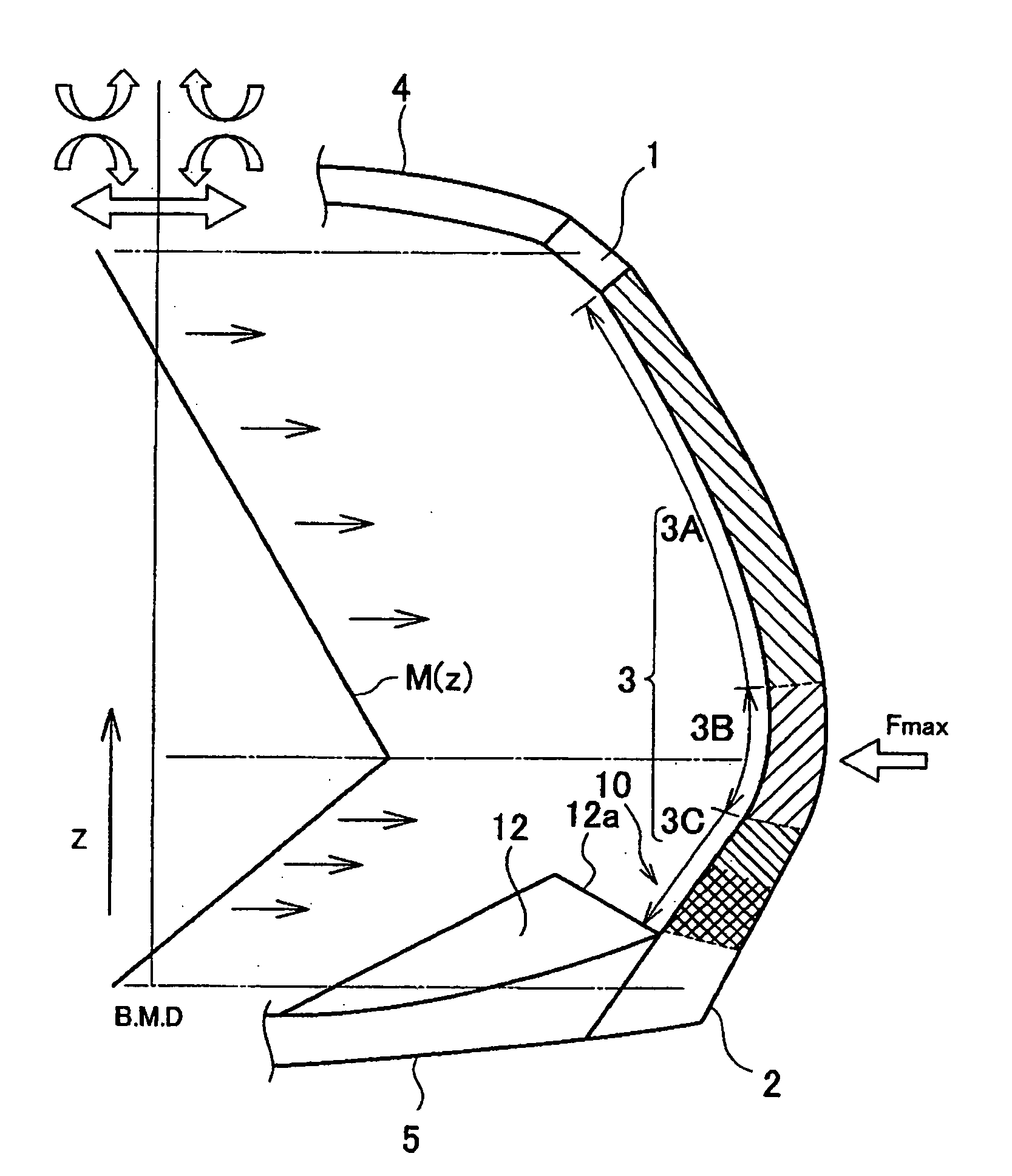
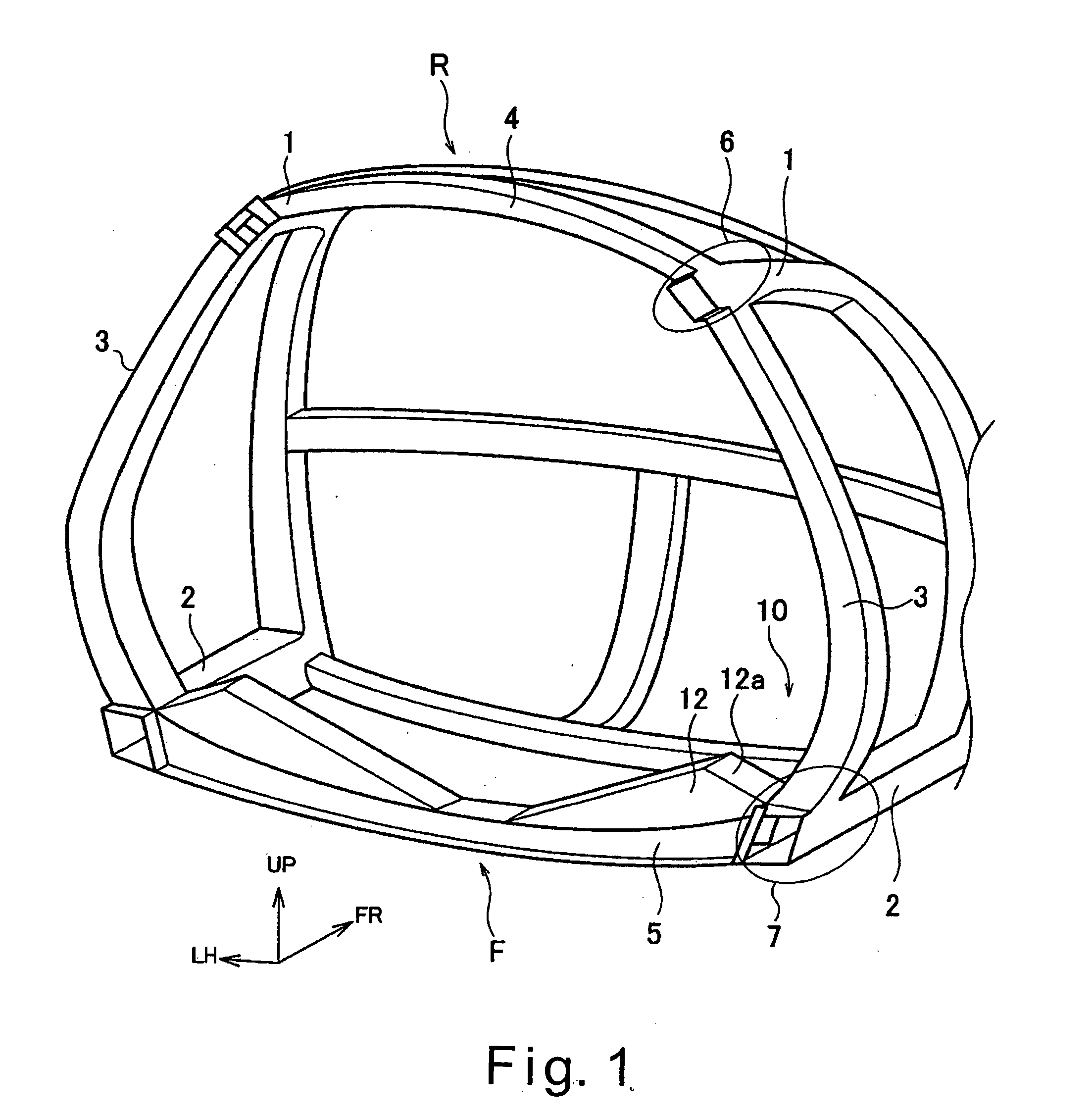
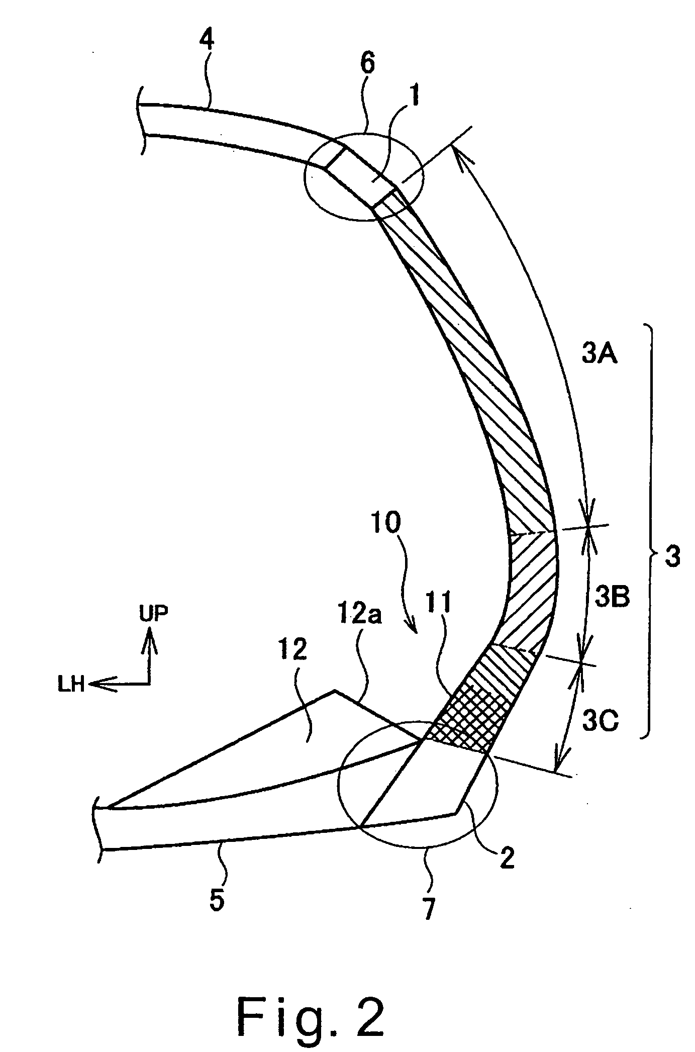
[0059] Referring initially to FIGS. 1-13, a vehicle body structure is illustrated in accordance with a first embodiment of the present invention. Basically, the lateral surface structure of the vehicle body structure in accordance with the first embodiment includes a pair of left and right side roof rails 1, a pair of left and right side sills 2, a pair of center pillars 3, a plurality of roof cross members 4 and a plurality of floor cross members 5.

[0060] The side roof rails 1 extend generally in a longitudinal direction of the vehicle (i.e., forward and backward along the vehicle body on both lateral sides of the vehicle) along the roof section R. The side sills 2 extend in a longitudinal direction of the vehicle along the vehicle body on both lateral sides of the vehicle on the floor section F. The center pillars 3 are curved pillar members that bow outwardly from the vehicle. The center pillars 3 connect the side roof rails 1 and the side sills 2 together in th...

Example

Second Embodiment

[0083] Referring now to FIG. 14, a vehicle body structure in accordance with a second embodiment will now be explained. In view of the similarity between the first and second embodiments, the parts of the second embodiment that are identical to the parts of the first embodiment will be given the same reference numerals as the parts of the first embodiment. Moreover, the descriptions of the parts of the second embodiment that are identical to the parts of the first embodiment may be omitted for the sake of brevity. FIG. 14 is a perspective view of a deformable section 11 provided to the lower pillar end section of a center pillar 3.

[0084] The vehicle body structure of the second embodiment has the beads 11a formed on the front and rear walls 3q and 3r of the lower pillar end section of the center pillar 3 as a deforming section, as shown in FIG. 14. Therefore, according to the second embodiment, essentially the same operational effects as the first embodiment are a...

Example

Third Embodiment

[0085] Referring now to FIGS. 15 and 16, a vehicle body structure in accordance with a third embodiment will now be explained. In view of the similarity between the first and third embodiments, the parts of the third embodiment that are identical to the parts of the first embodiment will be given the same reference numerals as the parts of the first embodiment. Moreover, the descriptions of the parts of the third embodiment that are identical to the parts of the first embodiment may be omitted for the sake of brevity.

[0086]FIG. 15 is a perspective view of the lower pillar end section of the center pillar 3, while Figure 16 is an enlarged cross-sectional view of the center pillar 3 as viewed along the section line G-G in FIG. 15. In the vehicle body structure of the third embodiment, the axial collapse strength increases in the longitudinal direction continuously or intermittently in the upward direction from the lowermost end connection to the side sills 2 of the c...


PUM


Abstract

A vehicle body structure is configured to convert a lateral-impact input to an input that acts on a pillar member in substantially a vertical direction of the vehicle body. The vehicle body structure has an input conversion structure configured to convert a side-impact input that acts inwardly on the pillar member in a substantially horizontal direction from the vehicle exterior to an input that is applied to the pillar member in the vertical direction of the vehicle body. Thus, the side-impact input can be converted as an input that is applied to the pillar member in the vertical direction of the vehicle body, so that the input can be absorbed as a compression load applied to the pillar member in the longitudinal direction, and deformation into the passenger compartment can be minimized.

Description

BACKGROUND OF THE INVENTION [0001] 1. Field of the Invention [0002] The present invention generally relates to a vehicle body structure for automobiles. More specifically, the present invention relates to a vehicle body structure that is configured to absorb the energy of a side impact. [0003] 2. Background Information [0004] Some conventional vehicle body structures have been proposed that include structures in which a strength discontinuity is provided to minimize localized bending of the center pillar of a vehicle. Specifically, the strength discontinuity is provided at a lower section of a center pillar with a closed cross-sectional structure around the entire circumference. Thus, the structure bends into the passenger compartment in an appropriate manner at the strength discontinuity during a side impact, such that localized bending at the middle area and the upper area of the center pillar is prevented. In other words, the center pillar is displaced into the passenger compartm...

Claims


Application Information

Patent Timeline
IPC IPC(8): B60J5/00B60J5/04B62D21/15B62D25/04B62D25/06B62D25/20
CPCB60J5/0429B60J5/043B62D25/2036B62D25/025B62D25/04B62D21/157
Inventor SAEKI, HIDETSUGU
Owner NISSAN MOTOR CO LTD
Why Eureka
Try Eureka