System and method for optimizing power usage in a radio frequency communication device

a radio frequency communication and power usage technology, applied in the field of system and method for optimizing power usage in radio frequency communication devices, can solve the problems of poor backscatter range, inefficient coupling of rectified signal input from the antenna to the comparator circuit, and low power consumption in mode, so as to optimize power consumption during listening mode, optimize backscatter range, and optimize power consumption

Inactive Publication Date: 2005-02-03
STEMCO LP
View PDF18 Cites 57 Cited by
  • Summary
  • Abstract
  • Description
  • Claims
  • Application Information

AI Technical Summary

Benefits of technology

[0021] A system and method for optimizing power consumption in an RF communication device of the present invention provides numerous advantages over prior RF communication device configurations. For example, the present invention advantageously provides optimization of backscatter range while also providing the ability to optimize power consumption during listening mode.

Problems solved by technology

The listening mode requires little power because the tag is essentially idle and waiting for a signal from the interrogator.
Unfortunately, in order to bias the diodes in an optimum fashion for backscatter purposes, a small resistor must be used for the load.
This means that when the tag is listening for a signal, the rectified signal input from the antenna will inefficiently couple to the comparator circuit.
However, this results in poor backscatter range.
Often the tag is optimized for power consumption during the listening mode, which decreases backscatter range, but prolongs battery life.

Method used


Image

  • System and method for optimizing power usage in a radio frequency communication device
  • System and method for optimizing power usage in a radio frequency communication device
  • System and method for optimizing power usage in a radio frequency communication device

Examples


Embodiment Construction

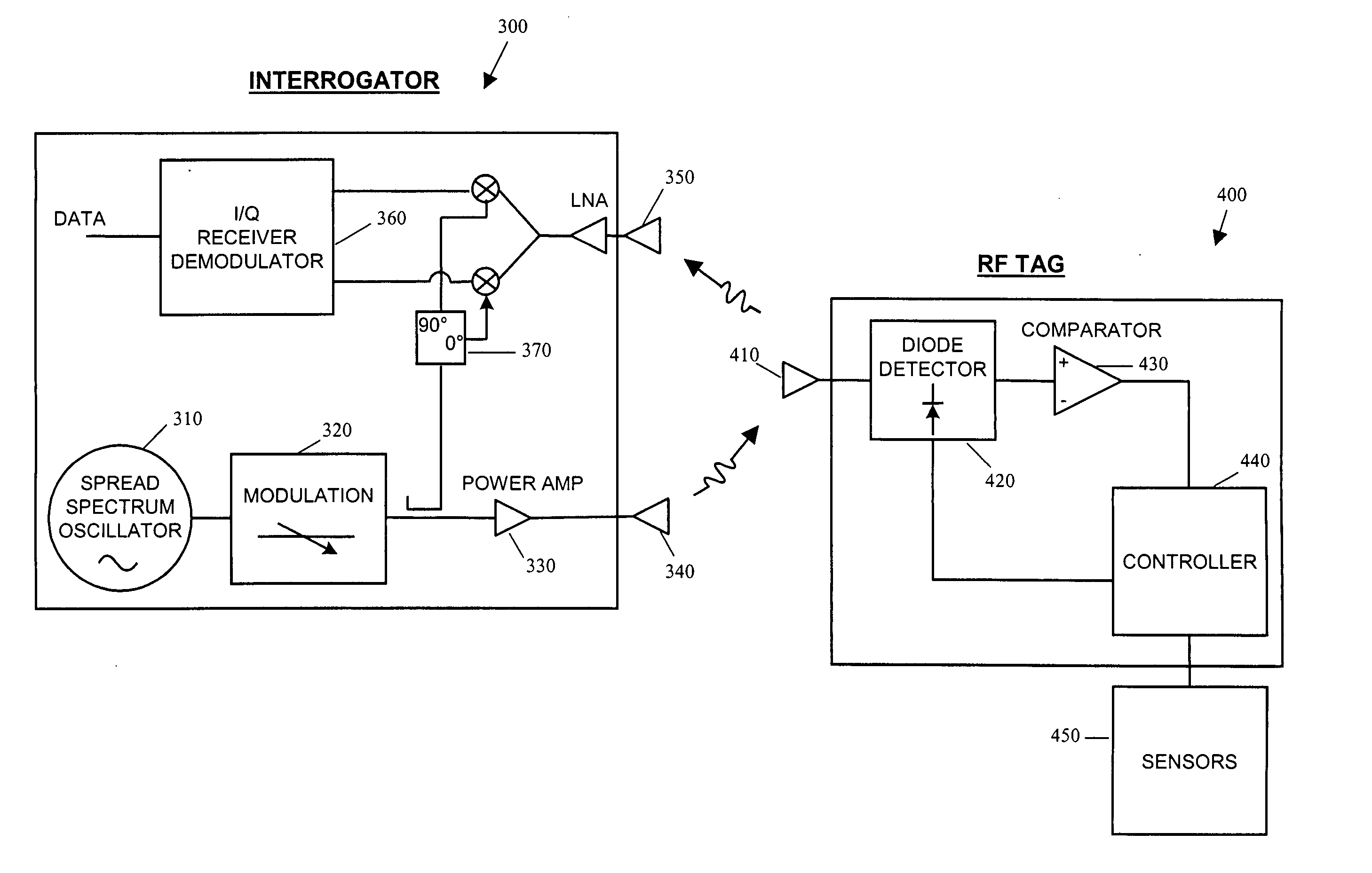
[0027] In a first aspect of the present invention, a radio frequency (RF) communication device is provided comprising means for switching between a low current operating mode and a high current operating mode. The low current operating mode is optimized to conserve power while the RF device is awaiting a wake-up signal from an interrogator. The high current operating mode is optimized to provide antenna matching during backscatter communications so as to maximize the range of backscatter communication between the RF device and the interrogator.

[0028] In a preferred embodiment of the present invention, the remote RF communication device comprises a radio frequency identification tag. The description of the preferred embodiments of the present invention will be discussed with reference to a RF tag and RF transponder as the RF communication device.

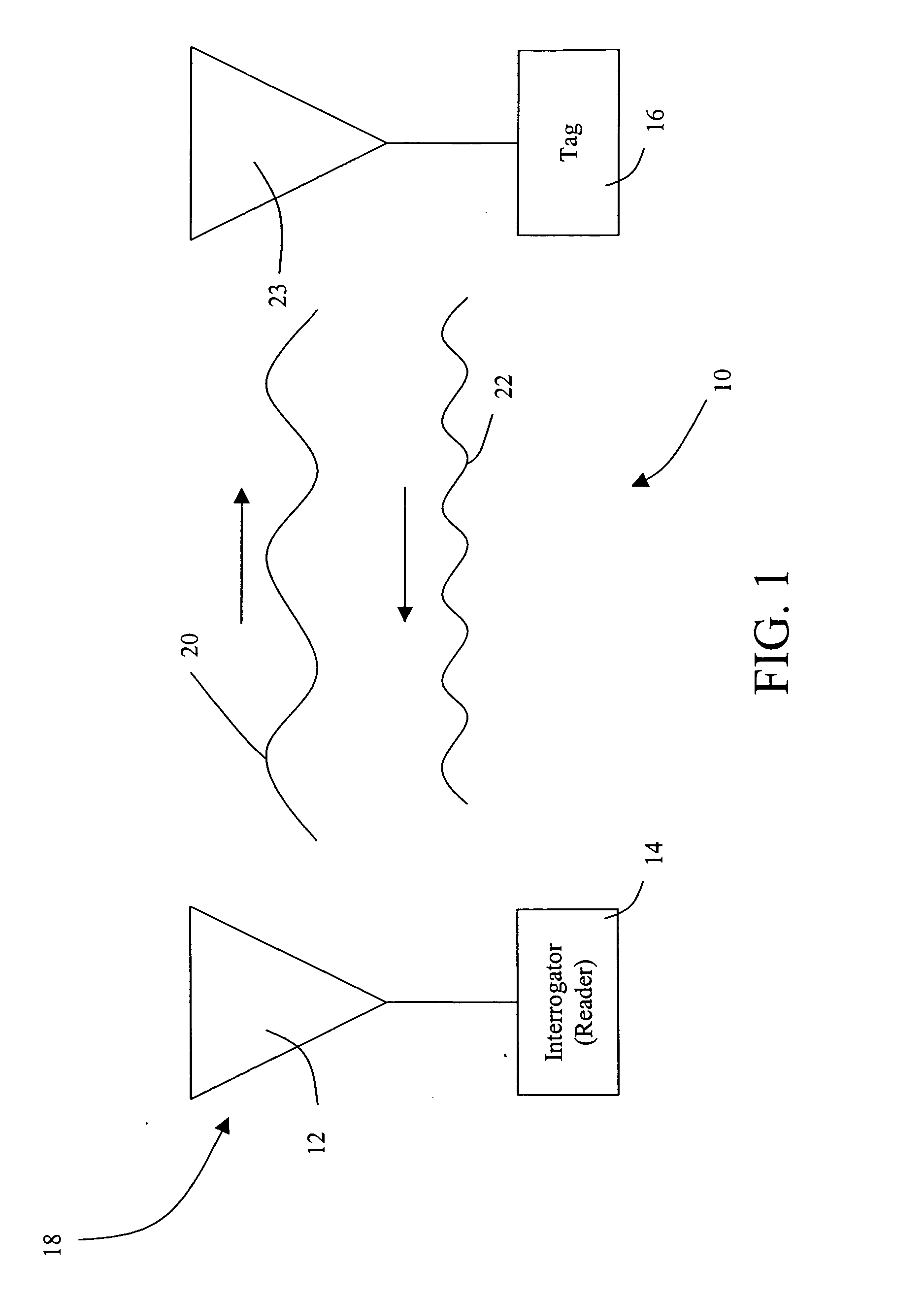
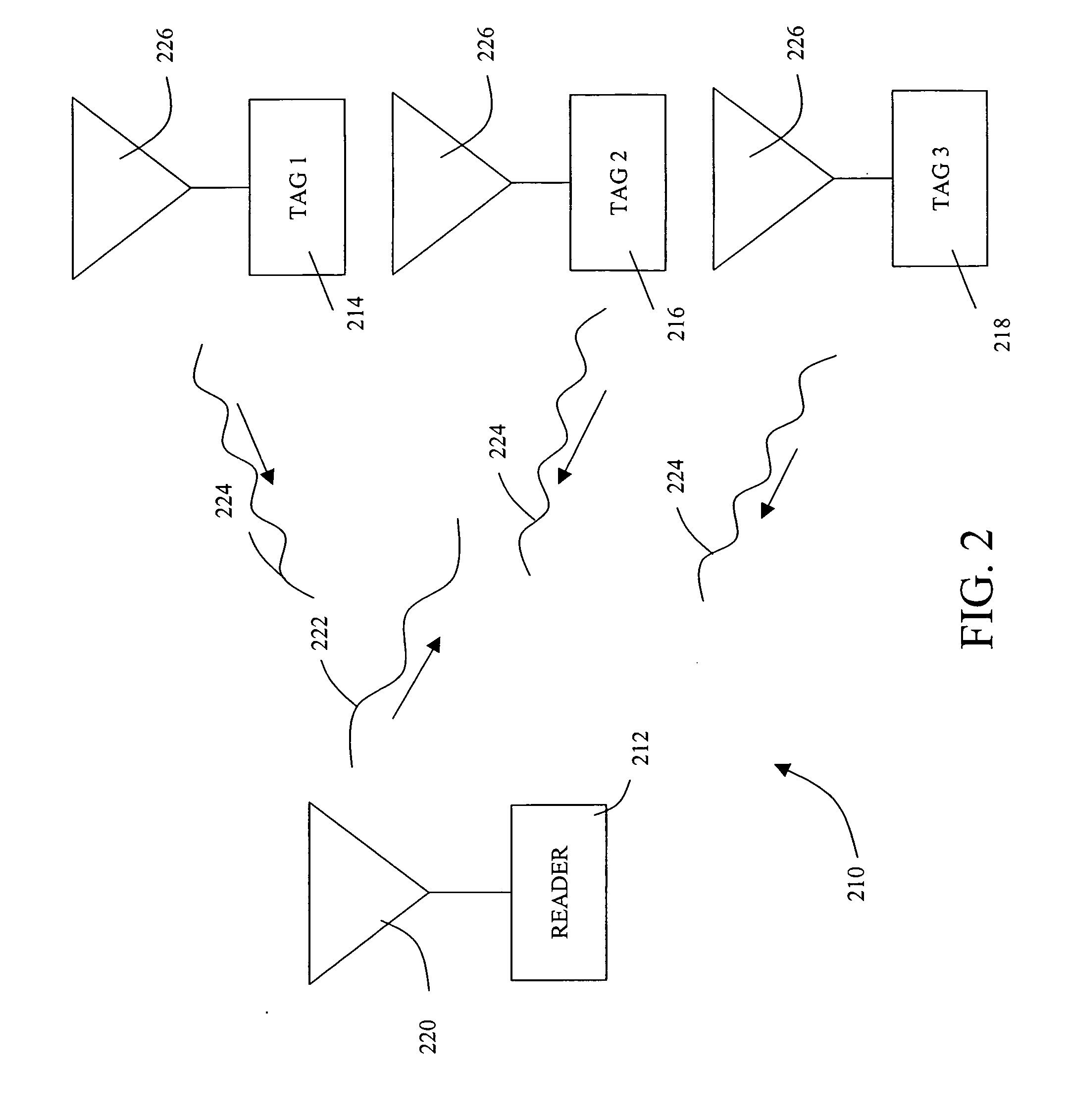
[0029] In one aspect of the present invention, the RF communication system comprises an interrogator and at least one RF communication dev...


PUM


Abstract

A radio frequency (RF) communication device is provided comprising means for switching between a low current operating mode and a high current operating mode. The low current operating mode is optimized to conserve power while the RF device is awaiting a wake-up signal from an interrogator. The high current operating mode is optimized to provide antenna matching during backscatter communications so as to maximize the range of backscatter communication between the RF device and the interrogator. Further provided, is a system and method for optimizing power consumption and backscatter range within an RF communication device.

Description

CROSS REFERENCE TO RELATED APPLICATIONS [0001] The present application claims priority under 35 U.S.C. § 119(e) from U.S. Provisional Patent Application Ser. No. 60 / 490,575 filed Jul. 28, 2003, entitled “Switchable Bias on Frequency Hopping RFID Tags”, the disclosure of which is incorporated herein by reference.FIELD OF THE INVENTION [0002] The present invention relates to systems and methods for increasing communication range and prolonging battery life in a radio frequency communication device. More particularly the present invention relates to systems and methods for improving the overall power usage of a radio frequency identification RFID device. BACKGROUND OF THE INVENTION [0003] Remote communication using wireless equipment may rely on radio frequency (RF) technology. One application of RF technology is in locating, identifying, and tracking objects, such as animals, inventory, and vehicles. Other applications of RF technology may include communication of data collected from ...

Claims


Application Information

Patent Timeline
Patent Type & Authority Applications(United States)
IPC IPC(8): G06K19/07H04BH04Q5/22
CPCG06K19/0707G06K19/0723G06K19/0712
Inventor KRANZ, MARK J.STEPH, JAMES C.
Owner STEMCO LP
Why Eureka
Try Eureka