Head-up display device

a display device and head-up technology, applied in the field of head-up display devices, can solve problems such as unattractive exteriors, and achieve the effects of low cost, simple structure, and small space for receiving the cover

Active Publication Date: 2005-02-03
YAZAKI CORP
View PDF5 Cites 54 Cited by
  • Summary
  • Abstract
  • Description
  • Claims
  • Application Information

AI Technical Summary

Benefits of technology

Therefore a space for receiving the cover can be small. That is, even in a vehicle, in which the distance between a duct and an instrument panel is small, the head-up display device can be received in the instrument panel. Further

Problems solved by technology

Further, upon nonuse the hinges 17 are also

Method used


Image

  • Head-up display device
  • Head-up display device
  • Head-up display device

Examples


Embodiment Construction

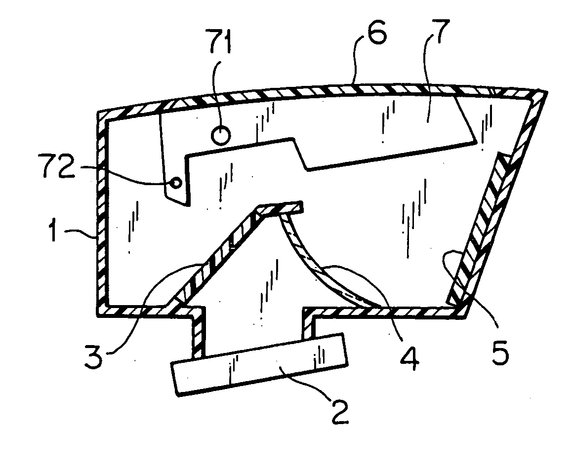
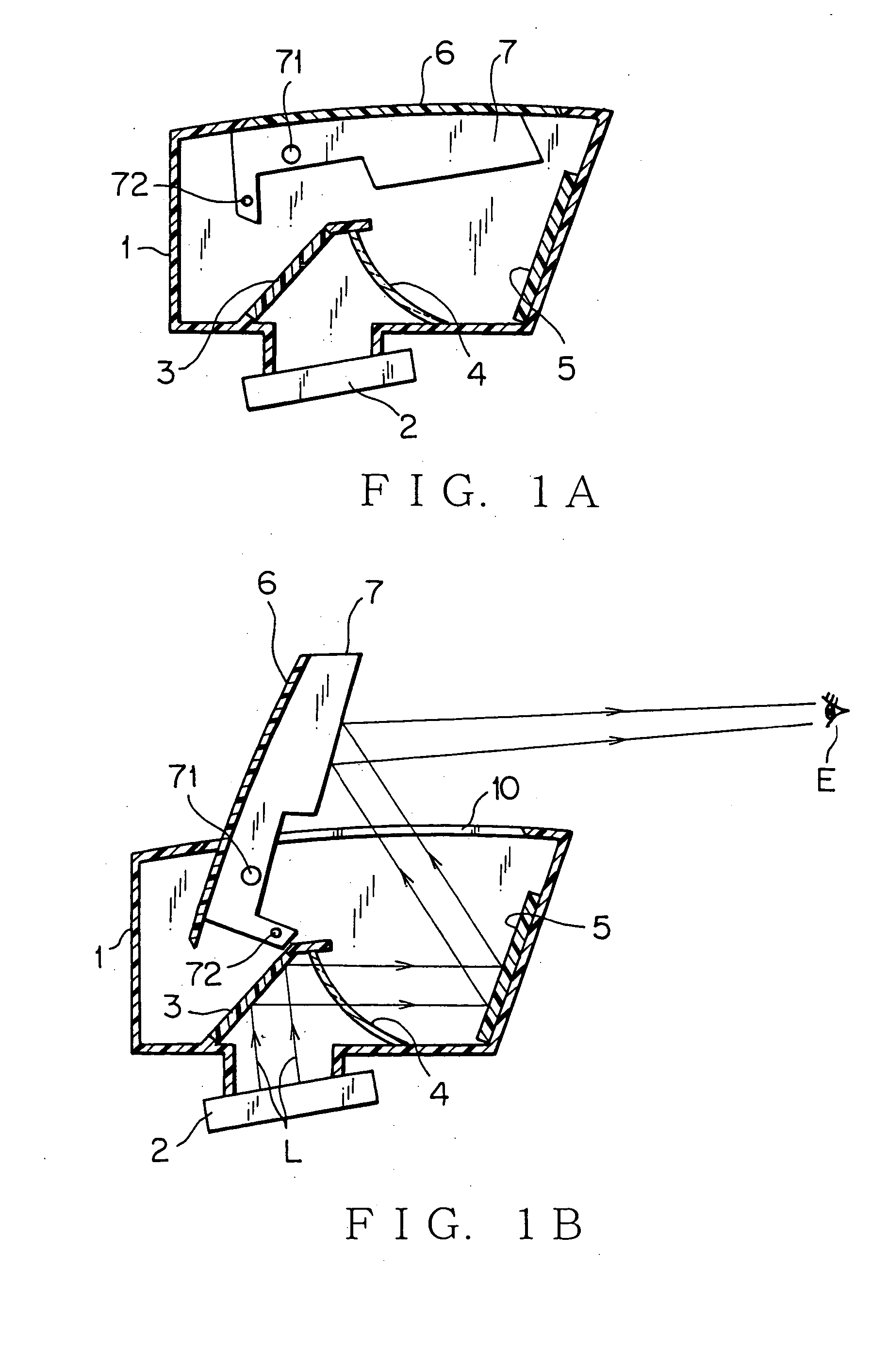
In the following, a first preferred embodiment of the present invention will be explained with reference to the attached drawings. FIGS. 1A and 1B illustrate states upon nonuse and use, respectively, of a head-up display device according to the first preferred embodiment of the present invention. FIGS. 1A and 1B are views viewed from the side.

As shown in FIGS. 1A and 1B, the head-up display device according to the first preferred embodiment of the present invention includes a display element 2 for emitting a specific image displaying light, first mirror 3, front glass 4, second mirror 5, cover 6 which has a shape equivalent to that of an aperture 10 formed on an upper surface of a housing 1, and a retractable reflector 7 that carries out its opening and closing motion being pivoted on a part of the housing 1. The display element 2, first mirror 3, front glass 4, second mirror 5, cover 6, and reflector 7 are all received in the housing 1.

The housing 1 is, for example, made of re...


PUM


Abstract

A head-up display device having an excellent appearance, which has a simple structure and an excellent design upon both nonuse and use, is provided. A cover having a shape equivalent to that of an aperture formed on an upper surface of a housing is attached on an upper surface of a retractable reflector. The cover slides on the upper surface of the reflector cooperating with a retractable motion of the reflector, thereby performing the opening and closing action of the aperture. When the reflector takes its falling-down posture, the reflector and its rotation shaft can be shielded from an eye range and the number of the parting lines can be reduced.

Description

BACKGROUND OF THE INVENTION (1) Field of the Invention The present invention relates to a head-up display device mounted on a vehicle and so on, and particularly to a head-up display device having a retractable reflector. (2) Description of the Related Art So far, an example of such a head-up display device has been disclosed in Japanese Patent Application Laid-Open No. H9-315182. This conventional example will be explained with reference to FIGS. 9A, 9B and 10. FIGS. 9A and 9B illustrate states upon nonuse and use, respectively, of a conventional head-up display device. FIG. 10 is a plan view of the conventional head-up display device shown in FIG. 9A upon nonuse. As shown in FIGS. 9A and 9B, the conventional head-up display device includes a display element 12 which is received in a box-shaped housing 11 and emits image displaying light such as navigation information, total reflection mirror 13, front side cover 14 that constructs the front side of the housing 11 and performs...

Claims


Application Information

Patent Timeline
IPC IPC(8): B60K35/00G02B27/01
CPCG02B2027/0156G02B27/0149
Inventor HARADA, TAKESHIFURUYA, YOSHIYUKIKAGEYAMA, HIDEAKI
Owner YAZAKI CORP
Why Eureka
Try Eureka