Supercharge Your Innovation With Domain-Expert AI Agents!

Office machine

a technology for office machines and machines, applied in the field of office machines, can solve the problems of not being able to easily use a machine by short users or physically disabled people in wheelchairs, and the problem of comparatively tall machines, so as to improve the ease of use of the operation uni

Inactive Publication Date: 2005-02-03
INADA YUKIKO +1
View PDF2 Cites 11 Cited by
  • Summary
  • Abstract
  • Description
  • Claims
  • Application Information

AI Technical Summary

Benefits of technology

"The present invention relates to an office machine with a movable operation unit. The operation unit can be fixed at a high position, making it difficult for short users or physically disabled people to use. The invention aims to solve this problem by providing an office machine with an operation unit that can be easily operated by users. The office machine has a housing, a processing unit, and an operation unit that can be moved with respect to the housing. The operation unit can be designed to be rotatable about a horizontal axis and movable in the frontward and backward direction, in the upward and downward direction, or in the leftward and rightward direction. This allows users to easily access and operate the machine."

Problems solved by technology

Therefore, there has been a problem that these machines can not easily be used by short users or physically disabled people in wheelchairs.
The same problem is shared by other office machines, especially, comparatively tall machines.

Method used


Image

  • Office machine
  • Office machine
  • Office machine

Examples


first embodiment

[0041] (First Embodiment)

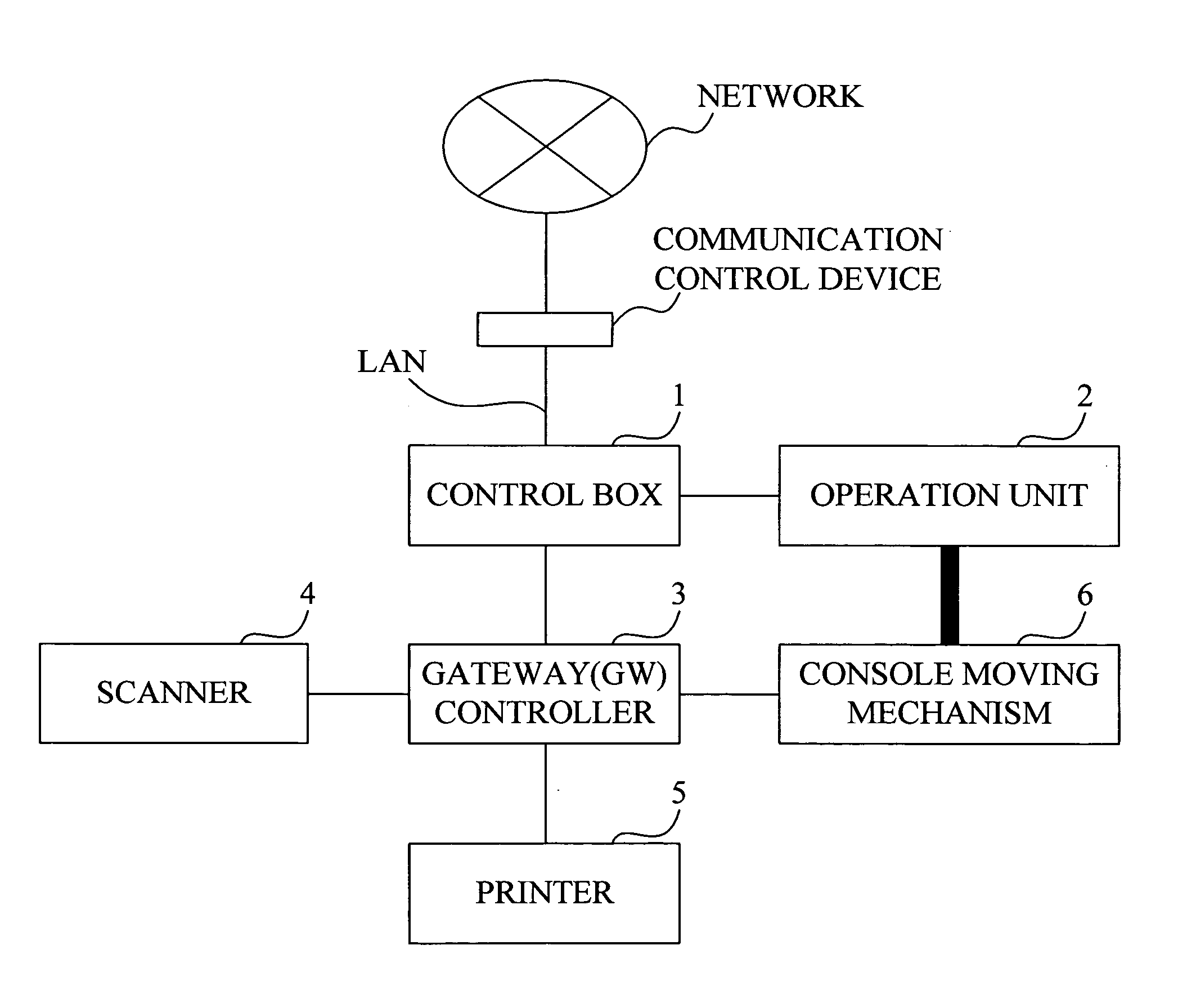
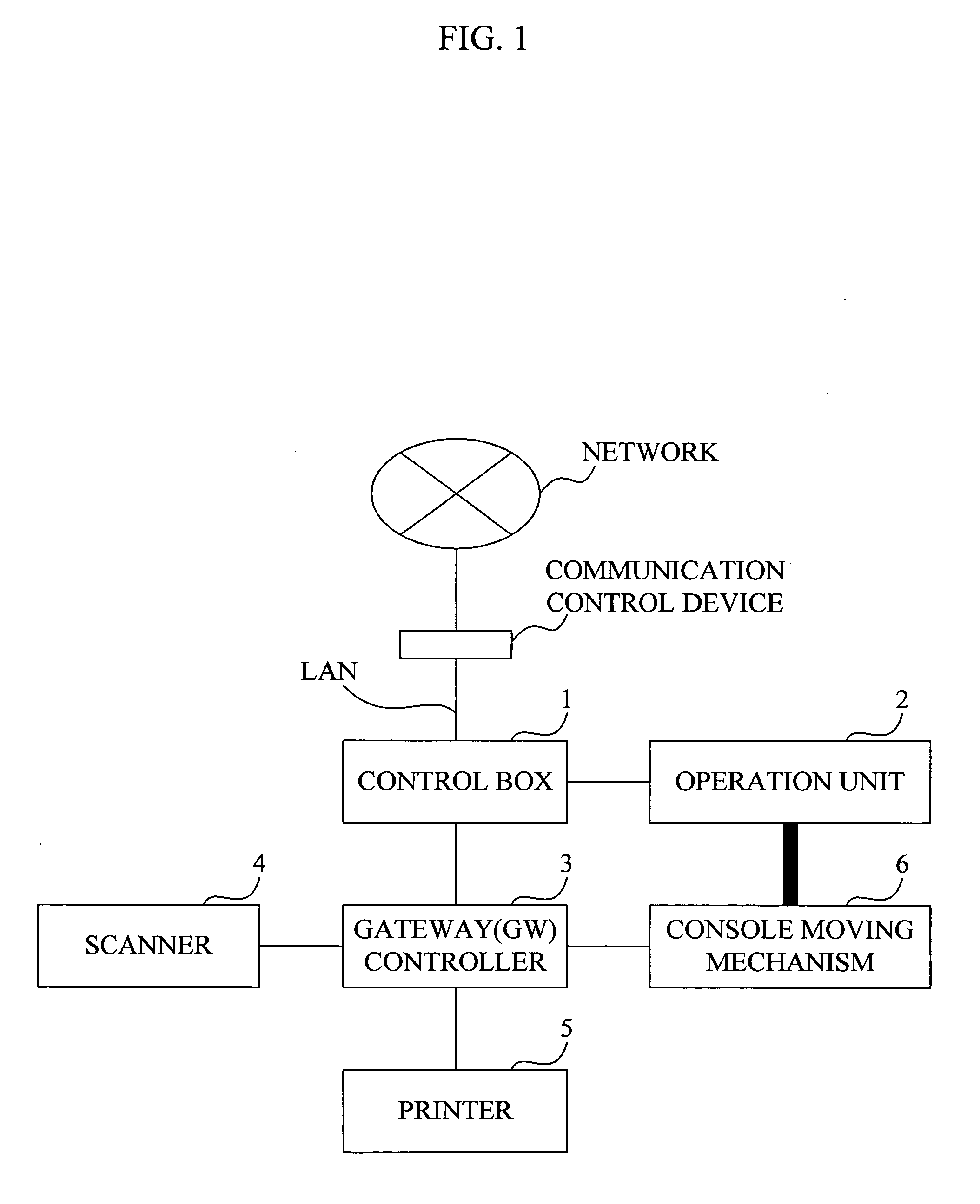
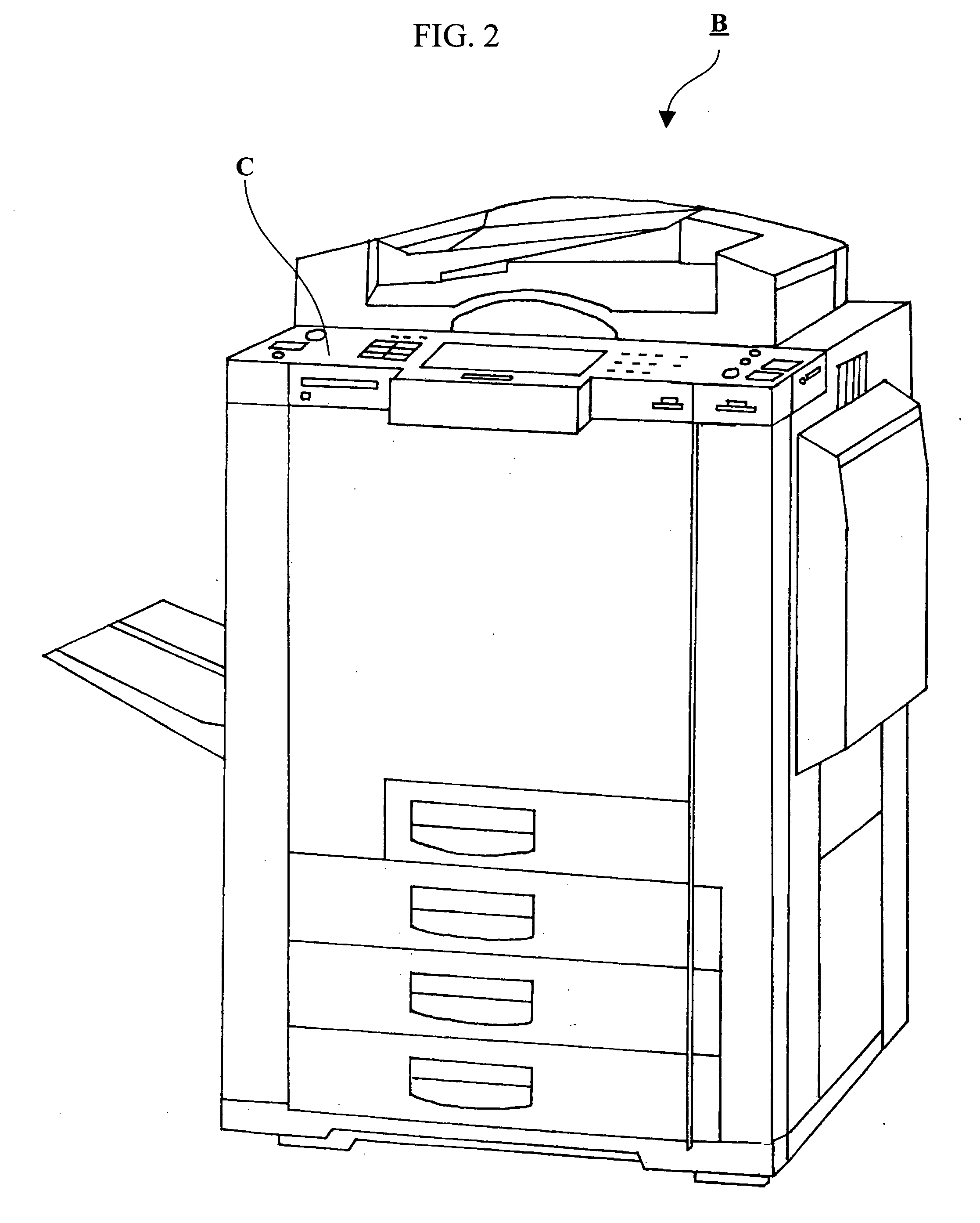
[0042]FIG. 1 is a diagram showing the configuration of a multifunction copying machine according to the first embodiment of the present invention. As shown in FIG. 1, this multifunction copying machine comprises a control box 1, an operation unit 2, a GW (GateWay) controller 3, a scanner 4, a printer 5, and a console moving mechanism 6. As shown in FIG. 2, this multifunction copying machine is formed as a complex machine having a housing B, and comprises a console section C. The console section C shown in FIG. 2 is mere a schematic diagram, and will be explained later in detail with reference to FIGS. 4A to 4D.

[0043] As shown in FIG. 3, the control box 1 comprises a control unit 11, a storage unit 12, and a network interface unit 13. The storage unit 12 and the network interface unit 13 are connected to the control unit 11 via an internal bus.

[0044] The control unit 11 comprises a processor such as a CPU (Central Processing Unit) or the like, a volatile me...

second embodiment

[0065] (Second Embodiment)

[0066]FIG. 10 is a diagram showing the configuration of a multifunction copying machine according to the second embodiment of the present invention. This multifunction copying machine according to the present invention comprises a control box 1, an operation unit 2, a GW controller 3, a scanner 4, a printer 5, and a robot arm 7, as shown in FIG. 10. As well as the above-described first embodiment, the present multifunction copying machine is formed as a complex machine having a housing B, and comprises a console section C.

[0067] The differences between the multifunction copying machine according to the present embodiment and the multifunction copying machine according to the first embodiment are that the multifunction copying machine of the present embodiment comprises the robot arm 7 in place of the console moving mechanism 6, and that the configuration of the operation unit 2 is changed in accordance with the replacement of the console moving mechanism 6...


PUM


Abstract

A console section having an operation unit is connected to a console moving mechanism. When an upward and downward sliding unit of the console moving mechanism moves upon a guide rail of a support pillar, the console section moves upward or downward. When a lateral direction sliding unit moves upon a guide rail of the upward and downward sliding unit, the console section moves in the lateral direction. When a frontward and backward sliding unit moves upon a guide rail of the lateral direction sliding unit, the console section moves frontward or backward. When a rotational moving unit rotates, the console section rotates. Due to these movements, a user can operate the operation unit by moving the console section to a position at which he / she can easily use the operation unit.

Description

BACKGROUND OF THE INVENTION [0001] 1. Field of the Invention [0002] The present invention relates to an office machine such as a multifunction copying machine, etc. and an operation unit thereof, and particularly to an office machine such as a multifunction copying machine, etc. having a movable operation unit. [0003] 2. Description of the Related Art [0004] Recently, multifunction copying machines which provide a function of generating hardcopies of document scripts, a function of sending and receiving facsimile data, and a function of reading (scanning) image data from scripts, all by themselves have become popular (for example, Unexamined Japanese Patent Application KOKAI Publication No. H11-202697). [0005] Generally, users of multifunction copying machines push a copying operation button when generating a copy, and click a print icon of a personal computer when printing a document or screen image from the personal computer. When using a scanner function, users put the script on ...

Claims


Application Information

Patent Timeline
Patent Type & Authority Applications(United States)
IPC IPC(8): B41J29/00G03G15/00G03G21/16G06F15/00H04N1/00
CPCG03G15/5016H04N1/00496H04N2201/0094G03G15/5087H04N1/00535G03G2215/00109H04N1/00533
Inventor INADA, YUKIKOFUJISHIGE, TAKEZO
Owner INADA YUKIKO
Features
  • R&D
  • Intellectual Property
  • Life Sciences
  • Materials
  • Tech Scout
  • Unparalleled Data Quality
  • Higher Quality Content
  • 60% Fewer Hallucinations
Learn More