

Reproduction system for video and audio signals
a technology of video and audio signals, applied in the field of video and audio signal reproduction systems, can solve the problems of difficult to provide a listening point to which the reflected sound is concentrated, and achieve the effect of easy front localization, good reproduction, and low cos
- Summary
- Abstract
- Description
- Claims
- Application Information
AI Technical Summary
Benefits of technology
Problems solved by technology
Method used
Image

Examples
embodiment 1
[0027] [Embodiment 1]
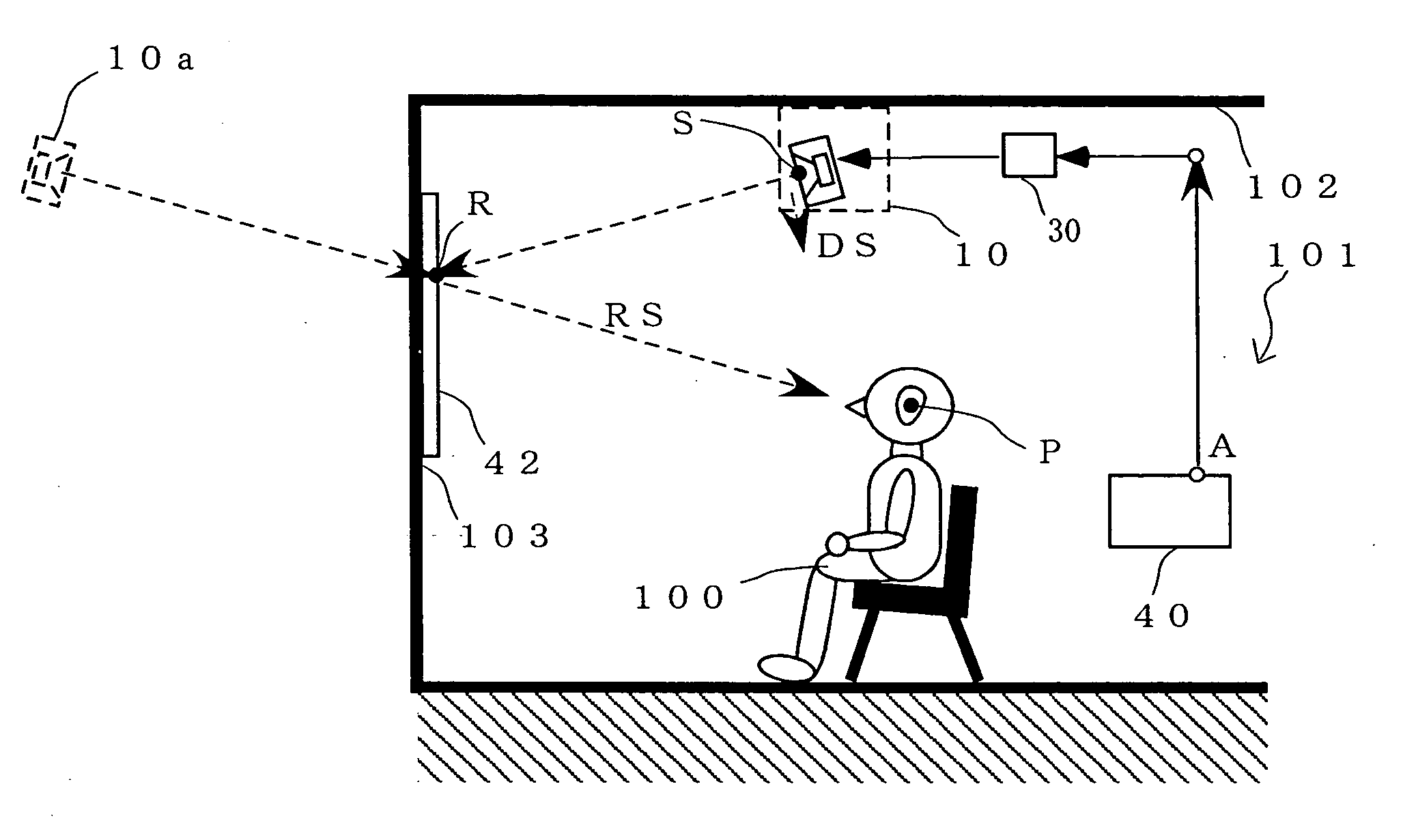
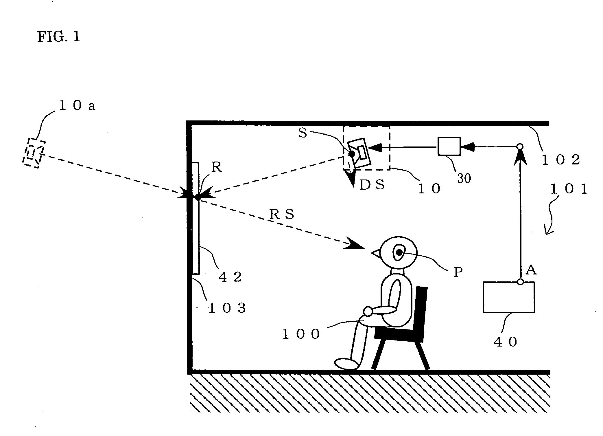
[0028]FIGS. 1 and 2 are views describing a reproduction system for an audio signal according to a preferable embodiment of the present invention. FIG. 1 is a side cross-sectional view of chamber 101, and FIG. 2 is a plan view of chamber 101. A speaker array 10 is disposed on a ceiling 102 above a viewer / listener 100 who is located at a listening point P within chamber 101. Reflection unit 42 is disposed on a wall surface 103 in the front. An audio signal A reproduced from a reproduction apparatus 40 passes through an amplifier 30 to be input into speaker array 10. Speaker array 10 is constructed with parallel connection of four speakers 11 to 14 having a diaphragm. Here, reproduction apparatus 40 may be representatively a visual acoustic apparatus such as a CD or DVD player.
[0029] In a reproduction system according to the present invention, the vibration direction of diaphragm S of each of the four speakers 11 to 14 of speaker array 10 is directed towards refle...
embodiment 2
[0032] [Embodiment 2]
[0033]FIG. 3 is a plan view describing a reproduction system for an audio signal according to another preferable embodiment of the present invention. Two viewers / listeners 100L and 100R are arranged to the right and left in chamber 101. In the case of providing an audio signal A from speaker array 10 to viewer / listener 100L located at a listening point PL and to viewer / listener 100R located at a listening point PR, the plural speakers 11 to 18 in speaker array 10 are divided into two sets (11 to 14) and (15 to 18) corresponding to the two listening points PL and PR. Thus, in the reproduction system according to the present invention, even if there are plural viewers / listeners, speaker array 10 may be divided into plural sets of speakers and, by setting the direction and position of the speakers in each speaker set, each viewer / listener can obtain an audio image localization in the direction of reflection unit 42. Thus, the increase in the synthesized level of th...
embodiment 3
[0035] [Embodiment 3]
[0036]FIG. 4 is a plan view describing a reproduction system for an audio signal according to another preferable embodiment of the present invention. In the illustrated case, the audio signal reproduced from reproduction apparatus 40 is a stereo signal composed of a left audio signal AL and a right audio signal AR. Left audio signal AL passes through amplifier 30L to be input into speaker array 10L, and right audio signal AR passes through amplifier 30R to be input into speaker array 10R. Speaker arrays 10L and 10R are constructed with parallel connection of four speakers 11 to 14 and 15 to 18 having a diaphragm. Here, the vibration direction of the diaphragm of each speaker is directed towards reflection unit 42, and the reflection path distance from the diaphragm of each speaker to listening point P, which defines a position of viewer / listener 100, via a reflection surface of reflection unit 42 is set to be equal.
[0037] As a result of this, the radiated sound...
PUM
 Abstract
Description
Claims
Application Information