Inspection apparatus and inspection method

a technology of inspection apparatus and mounting state, which is applied in the direction of image enhancement, instruments, image data processing, etc., can solve the problems of difficult to accurately detect these shapes, the time-consuming and labor-intensive value multiplexing process, and the inability to carry out image processing, etc., to achieve the possibility of further optimizing the illumination condition, extending the range of light source position, and detecting easily

Inactive Publication Date: 2005-02-03
TDK CORPARATION
View PDF16 Cites 25 Cited by
  • Summary
  • Abstract
  • Description
  • Claims
  • Application Information

AI Technical Summary

Benefits of technology

[0021] The second light source may be integrated with the camera and the first light source to form a unit in a similar manner as the first light source. In that case, the unit is moved parallel to the plane in which the board for mounting extends and the movement range is set in such a way that the board for mounting etc. always stays within the image pickup area of the camera, as described before. With this feature, the size of an image of the board for mounting etc. obtained with the first light source and the size of an image of the board for mounting etc. obtained with the second light source becomes equal to each other and the aforementioned advantageous effects are realized.
[0022] The first and second light sources may be adapted to be rotatable about a rotation axis that is perpendicular to their own optical axis. When the light source is rotated, the illumination condition of the radiated light for the board for mounting etc. is changed, so that the allowable range of the light source position can be extended. In addition, in order to pick up an image of the board for mounting etc. at a size smaller than a predetermined size within the image pickup area of the camera irrespective of the type of the board for mounting etc., it is preferable that camera be adapted to be movable in the direction perpendicular to the plane in which the board for mounting extends. In addition, in order to obtain a clear image, it is preferable that upon picking up an image of the board for mounting etc., the board be positioned at a point at which the optical axes of the first light source, the second light source and the camera intersect. Therefore, it is preferable that the first light source and the second light source be adapted in such a way that they can be rotated synchronously in accordance with the aforementioned movement of the camera in the perpendicular direction.
[0023] The unit may be constructed in such a way that only the second light source can be moved within the unit. In that case, the position of the second light source is changed while the position of the camera and the first light source is fixed, after an image of the board for mounting etc. is obtained under the state in which the image pickup condition with the camera and the first light source has been determined. With such a structure, an image of the same size of the board for mounting etc. can be obtained with the second light source while enlarging the adjustment range of the position of the second light source. Alternatively, at least one of the first and second light sources may be adapted to be rotatable so that the illumination condition can be further optimized by adjusting the light radiation direction by means of rotation of the light source.
[0024] As per the above, according to the present invention, even in the case that an image of an object including a part that requires adjustment of the position of a light source that radiates light, such as a solder paste or a transparent adhesive or the like, is to be picked up, a satisfactory image can be picked up while adjusting the position of the light source. Therefore, the contour of the mounted part or the edge of the fixing agent can be detected easily and the mounting state can be detected easily and accurately.

Problems solved by technology

However, if the difference in density (or light and shade) appearing on the board for mounting is small, the value multiplexing process sometimes takes a considerably long time.
Furthermore, in the case that the work piece has a complex contour, or in the case that the reflectance of the board for mounting, the reflectance of the adhesive and the reflectance of the work piece are close to each other and there are many undulations on their surfaces, it might be difficult to detect these shapes accurately based on the shade or the like obtained by simple illumination with light from one direction.
Even when the shade or the like is obtained, if mixed undulations are present in a bright area and the difference in density is extremely small, there is the risk that the image processing cannot be carried out.
Consequently, if a camera is disposed on the way of the direction in which the total reflection condition is met, an image in which only a specific portion has an extremely high brightness will be obtained, and it is very likely that the aforementioned appropriate image processing cannot be performed.
In that case., under some illumination conditions, such as in the case that light is cast onto the adhesive portion from a direction in which light is easily and totally transmitted, it is not possible to make the adhesive itself clearly visible, but an image of a member existing under the adhesive (e.g. the board for mounting) is picked up.
However, if the positional relationship between each light source and the camera is changed, the relationship between obtained images varies in accordance with the change in the aforementioned positional relationship, and therefore it is considered that simple comparison of the images can be inappropriate in some cases.
After all, in the technology disclosed in this prior art document, the object to be inspected is chipping of a chip or the like, and it is inappropriate to apply this technology directly to inspection of a structure containing, for example, a solder paste, an adhesive or the like, for which, as described above, it is necessary to select the light illumination condition or other conditions as needed.
Therefore, it is inappropriate to apply the technology disclosed in this prior art document directly to inspection of a structure containing, for example, a solder paste, an adhesive or the like, for which, as described above, it is necessary to select the light illumination condition or other conditions as needed.

Method used


Image

  • Inspection apparatus and inspection method
  • Inspection apparatus and inspection method
  • Inspection apparatus and inspection method

Examples


Embodiment Construction

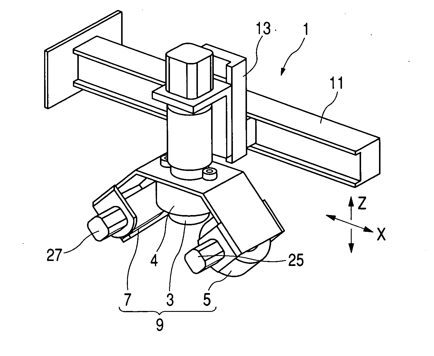
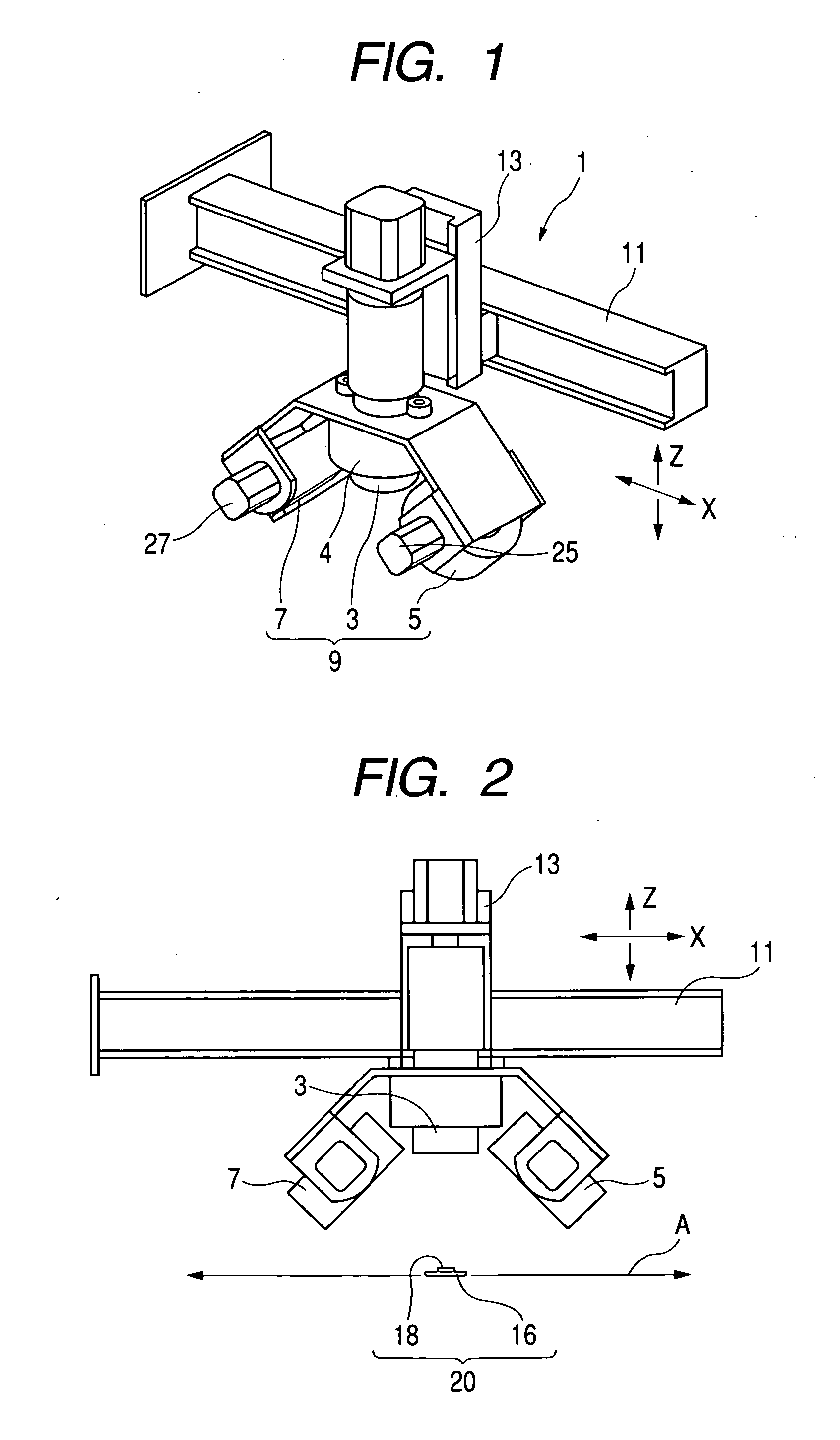
[0030]FIG. 1 is a perspective view showing an inspection apparatus according to an embodiment of the present invention, where the principal portion of the apparatus including a camera and first and second light sources are shown. The principal portion 1 of the inspection apparatus according to the present invention includes a unit 9 composed of a camera 3 directed vertically downwardly, an illumination light source 4 disposed coaxially with the camera 3, used for detection of a board and first and second light sources 5 and 7 disposed on both sides of the camera 3. The first and second light sources 5 and 7 are oriented toward a position below and on the axis of the camera 3. The unit 9 is supported by a first support rail 11 and a second support rail 13 in such a way that the unit 9 can be driven in the direction indicated by X and Z in FIG. 1. Various well-known mechanisms may be used as a driving mechanism for actually driving the unit 9 in the X and Z directions. The description...


PUM

PropertyMeasurementUnit
movable areaaaaaaaaaaa
areaaaaaaaaaaa
densityaaaaaaaaaa

Abstract

An object of the present invention is to provide a method for picking up, upon mounting an electronic part, an image of a board for mounting, a mounted part and a fixing agent that contain a potion such as an adhesive that transmits light so as to inspect the mounting state. In order to achieve the object, in the method according to the present invention, a camera disposed just above the board for mounting, a first light source disposed diagonally above the board and a second light source disposed diagonally above the board but at a position different from the first light source are integrated as a unit and they are moved in a direction substantially parallel to the board for mounting to determine the position of the first light source etc. at which the light transmissive portion can be preferably photographed.

Description

BACKGROUND OF THE INVENTION [0001] 1. Field of the Invention [0002] The present invention relates to an inspection method and an inspection apparatus for inspecting mounting state of a mounted part that has been mounted on a board for mounting by a part mounting apparatus. More specifically, the present invention relates to a method and an apparatus in which an image of a mounted part (which will be referred to as a work piece hereinafter) that has been fixed to a board for mounting by means of an adhesive or a solder paste is obtained and the mounting position or the mounting state thereof is detected based on the obtained image. [0003] 2. Related Background Art [0004] In the apparatus for inspecting mounting state, a board for mounting or a board on which a work piece(s) has been mounted is illuminated with illumination light and the illuminated state is photographed by a camera, so that the mounting position etc. is detected based on shading in the obtained image. The image proce...

Claims


Application Information

Patent Timeline
Patent Type & Authority Applications(United States)
IPC IPC(8): G01B11/00G01B11/24G01N21/956G06K9/00G06T7/00H01L21/00H05K13/08
CPCG06T7/0004H01L21/67259H01L21/67144G06T2207/30148
Inventor KANEKO, MASAAKINAKAYAMA, HITOSHISUZUKI, HIDETOSHI
Owner TDK CORPARATION
Why Eureka
Try Eureka