
Method and apparatus for shot detection

Inactive Publication Date: 2005-02-03
MICROSOFT TECH LICENSING LLC
View PDF47 Cites 13 Cited by
  • Summary
  • Abstract
  • Description
  • Claims
  • Application Information

AI Technical Summary

Benefits of technology

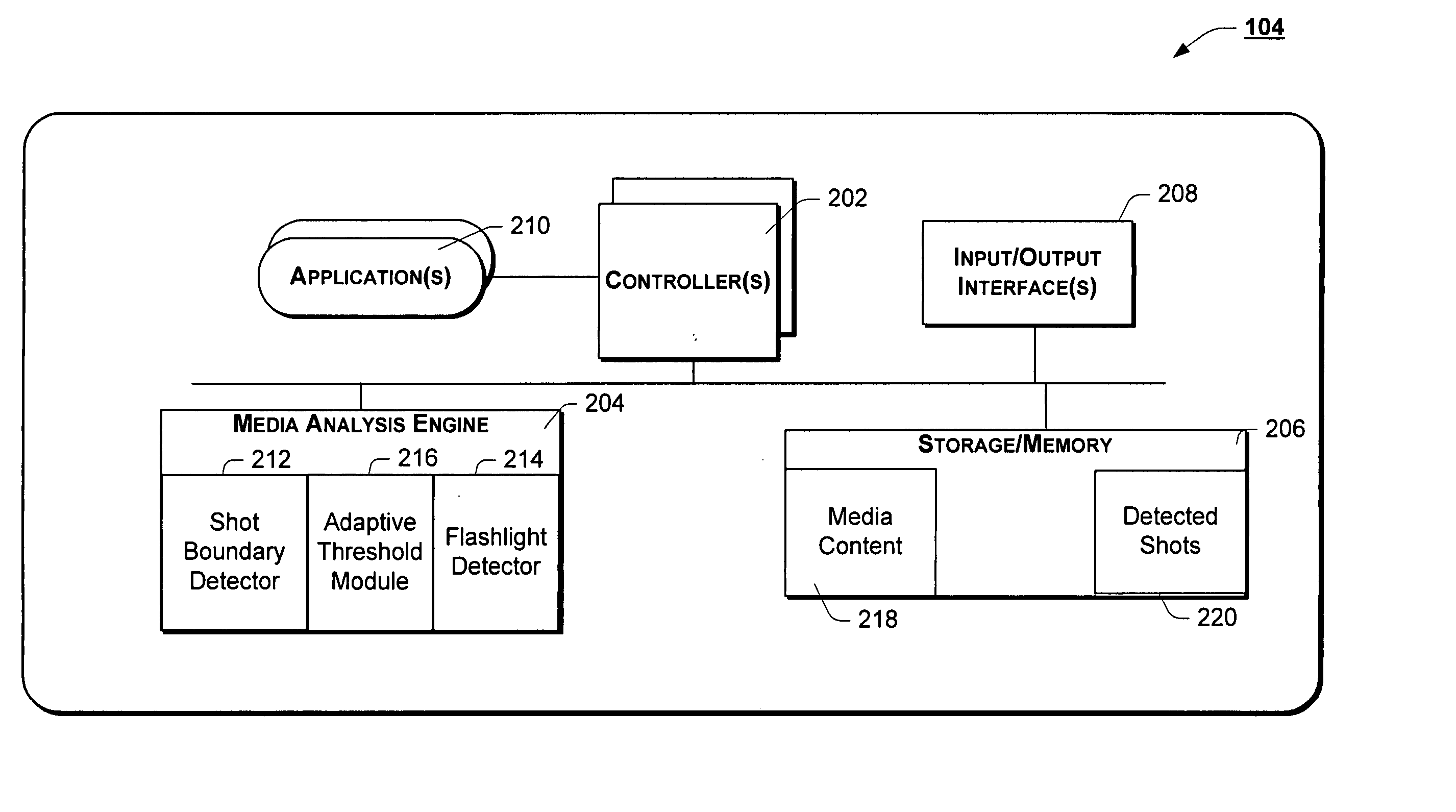
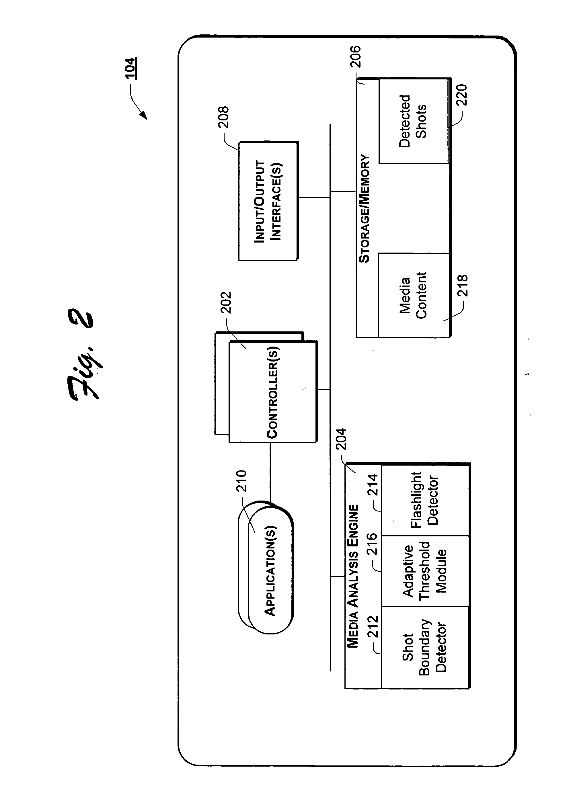
In another embodiment, a shot boundary detector statistically analyzes one or more attributes associated with content in video frames to detect abrupt and / or gradual transitions in the video content indicative of a shot boundary. A flashlight detector, responsive to the shot boundary detector, distinguishes abrupt transitions in the video content caused by flashlight events from those caused by actual shot boundaries, to reduce false-positive identification of flashlight events as shot boundaries.

Problems solved by technology

Conventional media processing systems fail to meet this expectation.
While the use of color histogram may prove acceptable in certain limited circumstances, it is prone to false shot boundary detection in many applications.
The result is that one shot of such news footage may include a number of light flashes (flashlight phenomena) which conventional shot boundary detection schemes mistake for shot boundaries.
The limitation of conventional shot boundary detection schemes is that they assume a flashlight only occurs across a single frame.
Another limitation of such conventional shot boundary detection schemes is that of threshold selection, i.e., the threshold of, for example, color histogram deviation that signals a shot boundary.
Global thresholds generally provide the worst performance as video properties often vary a lot and, quite simply, one size (threshold) does not fit all.
The local window based adaptive threshold selection method also has its limitations insofar as in certain situations, the local statistics are polluted with strong noises such as, for example, loud noises and / or flashlight effects.
Thus, a method and apparatus for shot boundary detection is presented, unencumbered by the inherent limitations commonly associated with prior art systems.

Method used


Image

  • Method and apparatus for shot detection
  • Method and apparatus for shot detection
  • Method and apparatus for shot detection

Examples


example operation and implementation

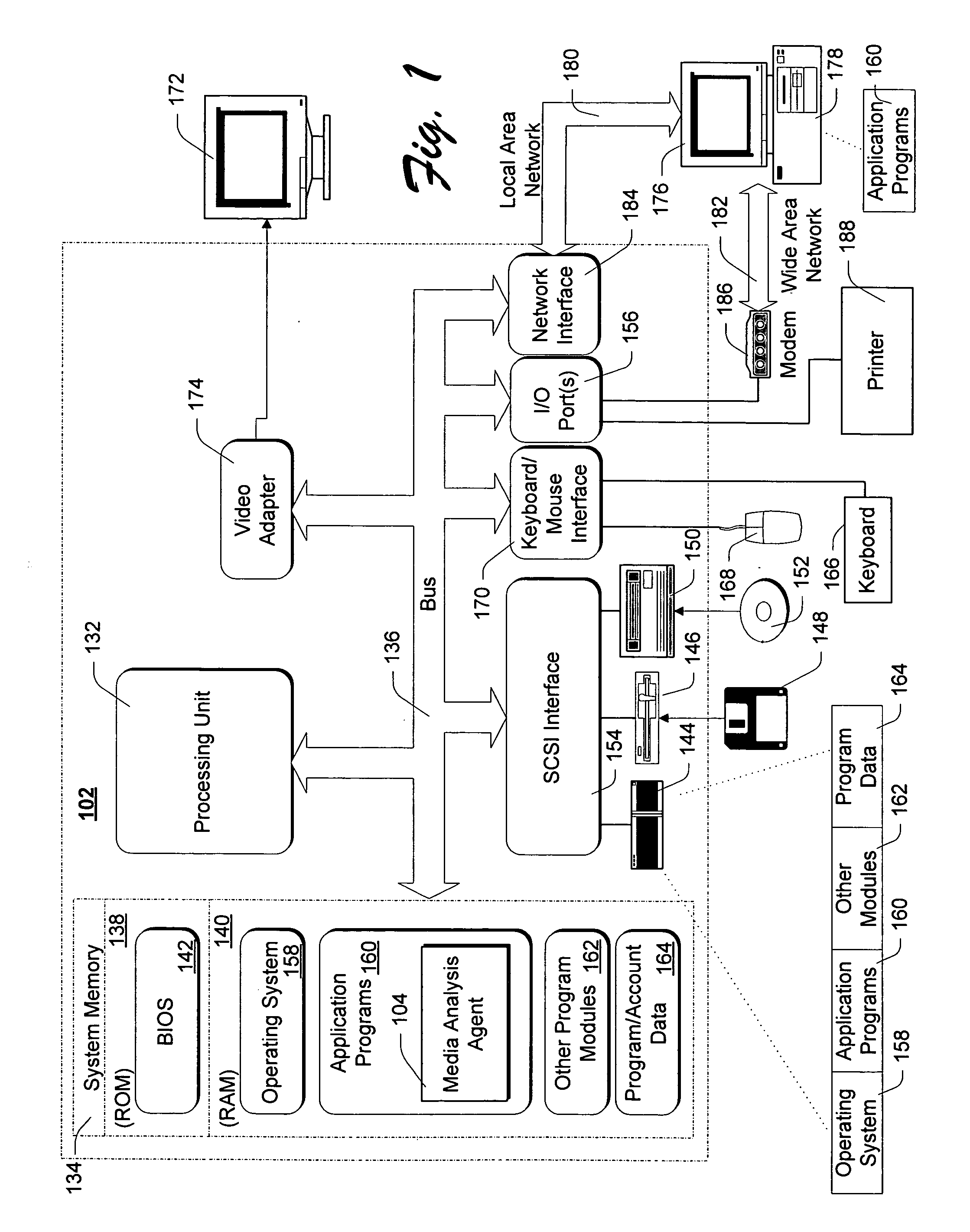
Having introduced the operating environment and functional elements of media analysis agent 104 with reference to FIGS. 1-4, above, the operation of the system will now be developed more fully below with reference to FIGS. 5-7, below. For ease of illustration, and not limitation, the operation of media analysis agent 104 will be developed below in the context of segmenting video content. However, as introduced above, the teachings of the present invention may well be adapted to segmenting other types of media content such as, for example, audio content.

FIG. 5 is a flow chart of an example method of shot boundary detection, according to one embodiment of the present invention. In accordance with the illustrated example implementation of FIG. 5, the method begins with block 502 wherein media analysis agent 104 receives an indication to segment media content into shots. In response, media analysis agent 104 selectively invokes an instance of shot boundary detector 212 of media analys...


PUM


Abstract

A system identifies an abrupt transition in content between two frames, and determines whether the abrupt transition was caused by a shot boundary between the two frames or by a flashlight event. Identification of the abrupt transition in content includes calculating a difference in light intensity histograms between the current frame and a preceding frame, and comparing the histogram difference to a dynamically determined threshold. Further, an average light intensity based method is used to determine whether the abrupt transition was caused by a shot boundary or by a flashlight event.

Description

TECHNICAL FIELD This invention generally relates to image processing and analysis and, more particularly, to a method and apparatus for shot detection. BACKGROUND With recent improvements in processing, storage and networking technologies, many personal computing systems have the capacity to receive, process and render multimedia objects (e.g., audio, graphical and video content). One example of such computing power applied to the field of multimedia C rendering, for example, is that it is now possible to “streammedia content from a remote server over a data network to an appropriately configured computing system for rendering on the computing system. Many of the rendering systems provide functionality akin to that of a typical video cassette player / recorder (VCR). However, with the increased computing power comes an increased expectation by consumers for even more advanced capabilities. A prime example of just such an expectation is the ability to rapidly identify, store and ac...

Claims


Application Information

Patent Timeline
IPC IPC(8): G06K9/00G06T7/20G11B27/28H04N5/14
CPCG06K9/00711H04N5/147G11B27/28G06T7/20G06V20/40
Inventor QI, WEIZHANG, DONG
Owner MICROSOFT TECH LICENSING LLC
Learn More