Ealuation system for vehicle operating conditions and evaluation method thereof

a technology of operating conditions and aluation systems, applied in the direction of relative volume flow measurement, process and machine control, instruments, etc., can solve the problem of excess fuel consumption cannot be computed, and engine output not being calculated from the amount of accelerator operation, etc. problem

Active Publication Date: 2005-02-03
MIYAMA
View PDF8 Cites 43 Cited by
  • Summary
  • Abstract
  • Description
  • Claims
  • Application Information

AI Technical Summary

Benefits of technology

An object of the present invention is to present useful information to the driver to improve operating techniques, and to enhance fuel economy by improving driving operation in a vehicle provided with a constant speed control device, an automatic transmission with a torque converter, or another automatic control device.
According to the present invention, a determination is made as to the operating state of the automatic control device installed in a vehicle based on the operating conditions of the vehicle, and the fuel amount consumed in excess (excess fuel consumption) by rapid acceleration or other type of driving that worsens fuel economy is computed with consideration given to the operating state of the automatic control device, and displayed to the driver. The driver can know of driving operations that cause fuel economy to worsen since driving that worsens fuel economy is immediately shown as an increase in excess fuel consumption and can improve driving operations with reference to this. The driver can be made aware of the degree that fuel economy worsened by his / her driving operation, and the driver can be prompted to improve his / her driving skill.
In vehicles comprising a constant speed control device or an automatic transmission with a torque converter serving as an automatic control device, the driver cannot directly command the gear position, but according to this invention the fuel amount consumed in excess by an inappropriate vehicle speed set in the constant speed control device, or inappropriate accelerator operation amount during automatic speed change can be shown to the driver, and driving skill can be improved even in vehicles with a constant speed control device, an automatic transmission or other automatic control device.
Adopting an approach in which the operating state of the automatic control device can be detected based on the vehicle operating conditions makes it easier to install this system in a vehicle and prevents the automatic control device from malfunctioning due to signal wire work or the like.

Problems solved by technology

Consequently, when an attempt is made to apply this system to a vehicle provided with a constant speed control device (automatic cruise controller), the engine output cannot be calculated from the accelerator operation amount and the engine rotational speed because the accelerator is not depressed while the constant speed control device is operating, and the excess fuel consumption cannot be computed as a result.
When this system is further applied to a vehicle provided with an automatic transmission with a torque converter, slippage occurs in the turbine and the torque converter pump, a discrepancy between work performed by the engine and work actually performed by the driving wheel arises due to the effect of the transmission efficiency of the torque converter, and the excess fuel consumption cannot be accurately computed.
Thus, an instructional method in which a higher speed gear is used to the extent possible while accelerating and running at constant speed, cannot be adopted.

Method used


Image

  • Ealuation system for vehicle operating conditions and evaluation method thereof
  • Ealuation system for vehicle operating conditions and evaluation method thereof
  • Ealuation system for vehicle operating conditions and evaluation method thereof

Examples


Embodiment Construction

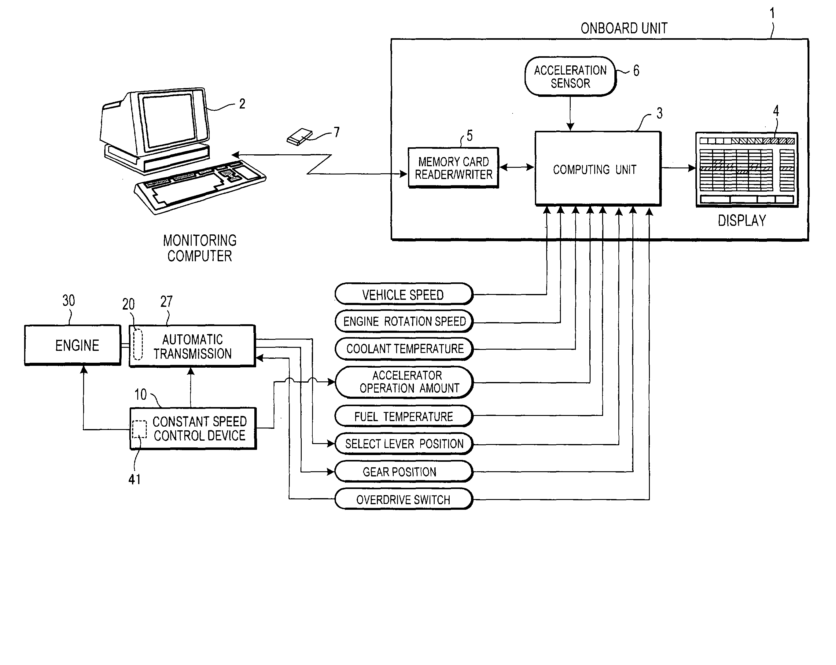
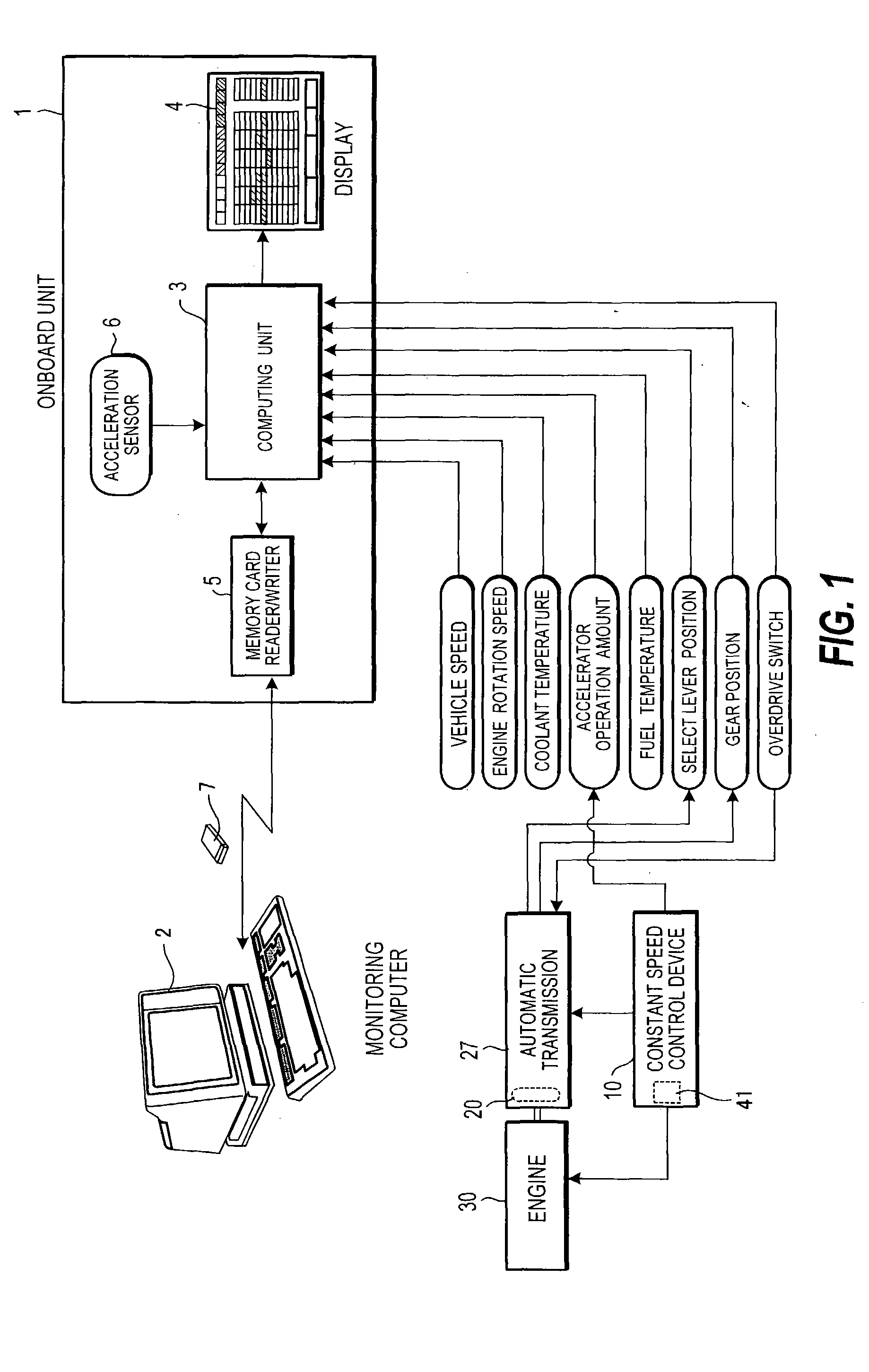
FIG. 1 of the drawings is a block diagram showing the structure of the evaluation system for vehicle operating conditions related to the present invention, and shows the case in which application has been made to a vehicle provided with a constant speed control device 10 such as an auto cruise controller, and an automatic transmission 27 with a torque converter 20. This system comprises an onboard unit 1 mounted in the vehicle, which is the object of evaluation, and a monitoring computer 2 for monitoring the vehicle.

The onboard unit 1 comprises a computing unit 3 which includes a CPU, memory, and an input / output interface; a display 4 such as an LCD; a memory card reader / writer 5; and a built-in acceleration sensor 6. The display 4 is mounted in the vehicle in a position easily viewable by the driver.

The computing unit 3 receives a vehicle speed (the rotational speed of the driving wheel or driving axle) signal, a rotational speed signal of an engine 30, a coolant temperature sig...


PUM


Abstract

The evaluation system for vehicle operating conditions comprises an automatic control device (10, 27) for setting target vehicle operating conditions and controlling the vehicle so as to achieve the target operating conditions, and a display device (4) mounted on the vehicle. The system determines whether operation that worsens fuel economy has been performed or not on the basis of the operating conditions of the vehicle; determines the operating state of the automatic control device (10, 27) based on the operating conditions of the vehicle; computes the excess fuel consumption, which is the fuel amount consumed in excess by operation that worsens the fuel economy, based on operating conditions of the vehicle and the operating state of the automatic control device (10, 27); and displays the computed excess fuel consumption to the display device (4).

Description

BACKGROUND OF THE INVENTION 1. Field of the Invention The present invention relates to a system for evaluating fuel economy and other vehicle operating conditions. 2. Description of the Related Art The fuel economy display device disclosed in JP2000-205925A, which was published in the year 2000 by the Japan Patent Office, computes fuel consumption on the basis of the fuel injection pulse signal outputted from the engine control unit, computes the traveled distance on the basis of the vehicle speed pulse signal outputted from the vehicle speed sensor, and computes and displays the fuel economy by dividing the computed traveled distance by the fuel consumption. However, simply displaying the fuel economy cannot be said to be sufficient in aiding in the improvement of driving skills because it cannot be known how the driver can specifically improve driving operation to enhance fuel economy, and to what degree fuel economy is further enhanced by improving driving operation. SUMMARY ...

Claims


Application Information

Patent Timeline
Patent Type & Authority Applications(United States)
IPC IPC(8): G01F9/02G06F7/00
CPCB60K2350/1092G01F9/023B60K2370/174Y02T10/84
Inventor MINAMI, KATSUAKIKUMAGAI, SATOSHIHAMURO, TAKAONAGAHARA, HIDEKI
Owner MIYAMA
Why Eureka
Try Eureka