
Side hook for shower curtain

a side hook and shower curtain technology, applied in the direction of curtain accessories, press-button fasteners, curtains, etc., can solve the problems of affecting the economic and affecting the use of the side hook. , to achieve the effect of saving the cost of processing, boosting the economical efficiency of the side hook structure thereof, and being convenient and properly applied

Inactive Publication Date: 2005-02-10
CHING FENG BLINDS INC CO LTD
View PDF14 Cites 15 Cited by
  • Summary
  • Abstract
  • Description
  • Claims
  • Application Information

AI Technical Summary

Benefits of technology

The present invention provides a side hook for a shower curtain that can be easily and properly applied in horizontal or vertical directions onto walls disposed at both lateral sides of a shower curtain via the double-sided adhesive tape thereof to locate the shower curtain in closing manner. The side hook has fixing teeth that securely locate the shower curtain thereto without any other holes further processed at both lateral sides thereof, economically saving the cost of processing. The fixing teeth of the base and the arc flexible plate thereof precisely clamp the shower curtain at both lateral sides thereof for secure location thereto without coming off there-from easily.

Problems solved by technology

There are some drawbacks to such conventional side hook for a shower curtain.
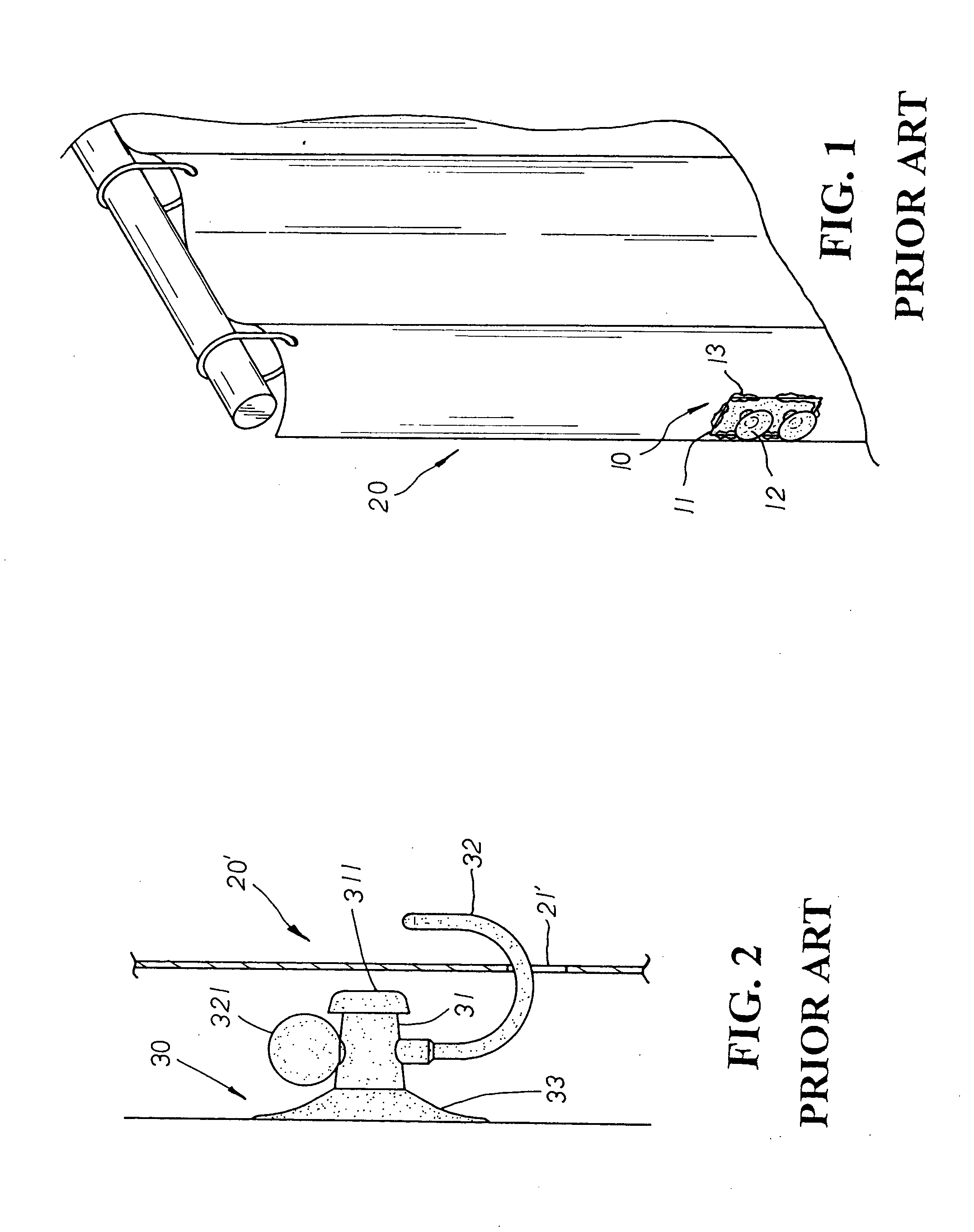
It not only mars the overall look of the shower curtain 20 in display, but also causes the imprecise fastening of the closing body 10 thereof and thus the chance of the defectives produced therewith.
Second, the suction cups 12 attached at one side of the closing body 10 are also fixed thereto via ultrasonic waves in welding art, which, tedious and time-consuming, may boost the costs of materials and processing thereof.
There are some disadvantages to the second conventional side hook for shower curtain.
Thus, the shower curtain 20′ must be further processed to provide the through hole 21′ at both lateral sides thereof respectively for hooking location thereof, which uneconomically increases the costs of processing and materials.

Method used


Image

  • Side hook for shower curtain
  • Side hook for shower curtain
  • Side hook for shower curtain

Examples


Embodiment Construction

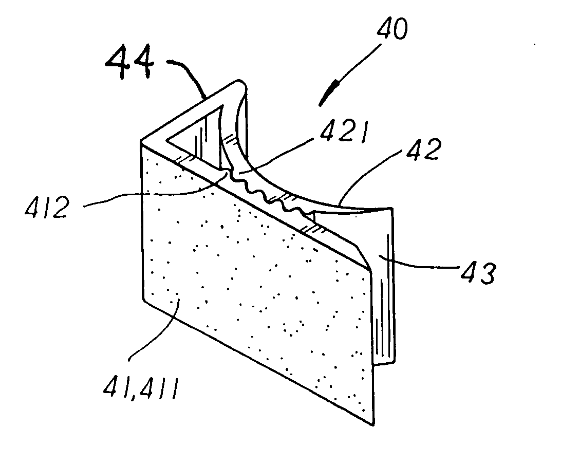
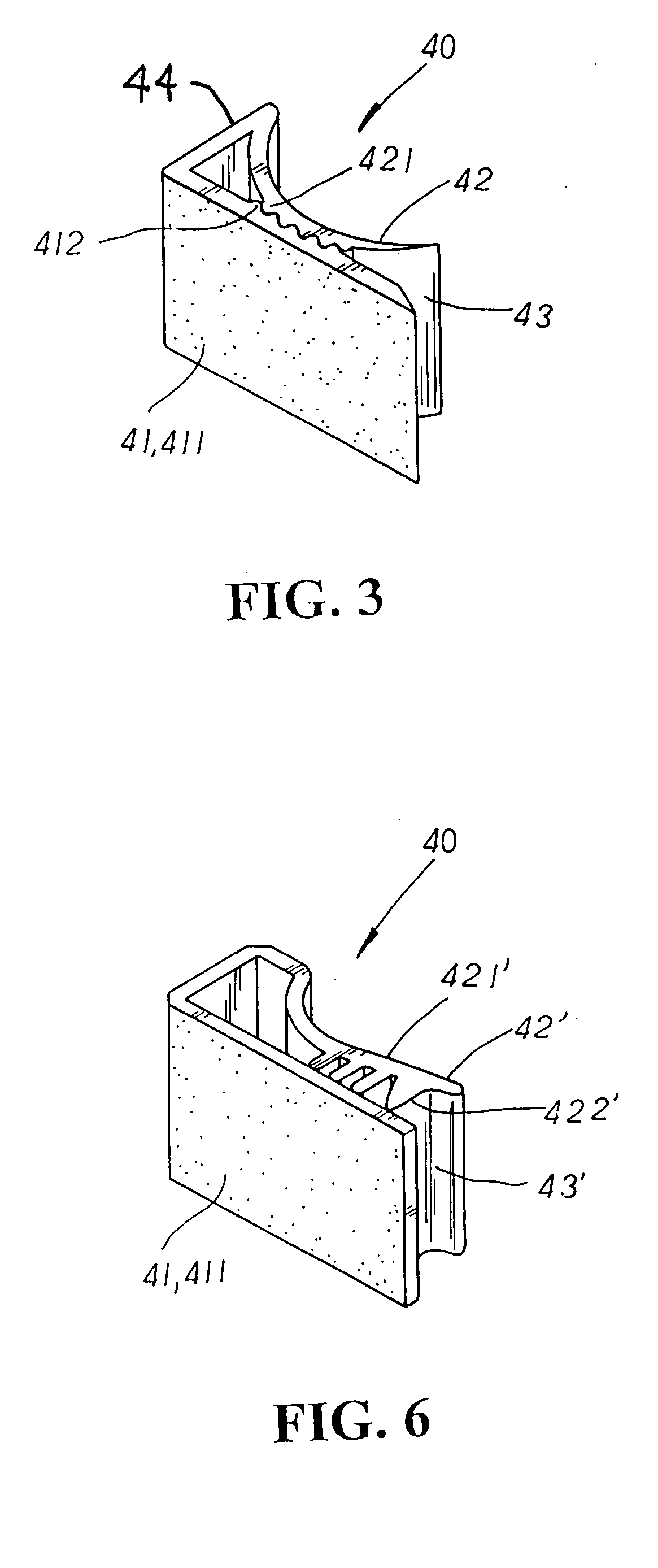
[0015] Please refer to FIG. 3. The present invention is related to a side hook for a shower curtain, mainly made up of a fixing clip 40 having a base 41 with a double-sided adhesive tape 411 applied thereon disposed at one side thereof, and an arc flexible plate 42 disposed at the other side thereof. A clamping passage 43 is disposed at the space defined by the bottom ends of the base 41 and the arc flexible plate 42 there-between, and fixing teeth 412, 421 are protruded at the corresponding inner side of the base and the arc flexible plate thereof respectively in clamping abutment.

[0016] In practical use, two fixing clips 40 are properly applied onto walls 51 disposed at both sides of a bath tub 50 via the double-sided adhesive tape 411 of the base 41 thereof. According to the location of the walls 51 thereof, the fixing clips 40 are attached either horizontally to the walls extending in straight line at both sides of the bath tube 50 as shown in FIG. 4, or vertically to the walls...


PUM


Abstract

A side hook for a shower curtain is mainly made up of a fixing clip having a base with a double-sided adhesive tape applied thereon disposed at one side thereof, and an arc flexible plate disposed at the other side thereof wherein a clamping passage is defined at the bottom ends of the base and the arc flexible plate there-between, and fixing teeth are correspondingly protruded at the inner side of both the base and the arc flexible plate respectively in clamping abutment. In practical use, the lateral sides of a shower curtain are pushed through the clamping passage of the fixing clip to be clamped tight by the fixing teeth therein for secure location of the shower curtain in closing manner. Besides, the fixing clip can also have a flexible plate with an arc slope and a plane section extending at one side thereof. Fixing teeth are protruded at the inner side of the plane section thereof in clamping abutment with the base thereof for precise location of the shower curtain thereof.

Description

BACKGROUND OF THE INVENTION [0001] The present invention is related to a side hook for a shower curtain, mainly made up of a fixing clip having a base with double-sided adhesive tape applied thereon disposed at one side thereof, and an arc flexible plate disposed at the other side thereof wherein a clamping passage is defined at one end of the base and the arc flexible plate, and fixing teeth are protruded at the corresponding inner side of the base and the arc flexible plate respectively in clamping abutment; whereby, via the clamping design of the fixing clip, a shower curtain is easily and securely located in closing manner without any other holes further processed at both lateral sides thereof, economically saving the cost of processing to boost the economical efficiency of the side hook structure thereof. [0002] Please refer to FIG. 1. A conventional side hook for a shower curtain is mainly made up of a closing body 10 having a fastening face 11 disposed at one side thereon to ...

Claims


Application Information

Patent Timeline
Patent Type & Authority Applications(United States)
IPC IPC(8): A47K3/38
CPCY10T24/44855A47K3/38
Inventor HSU, BEN
Owner CHING FENG BLINDS INC CO LTD
Learn More