Control system for hybrid vehicle

US20050029023A1Active Publication Date: 2005-02-10AISIN AW CO LTD +1

Image

  • Control system for hybrid vehicle
  • Control system for hybrid vehicle
  • Control system for hybrid vehicle

Examples


Embodiment Construction

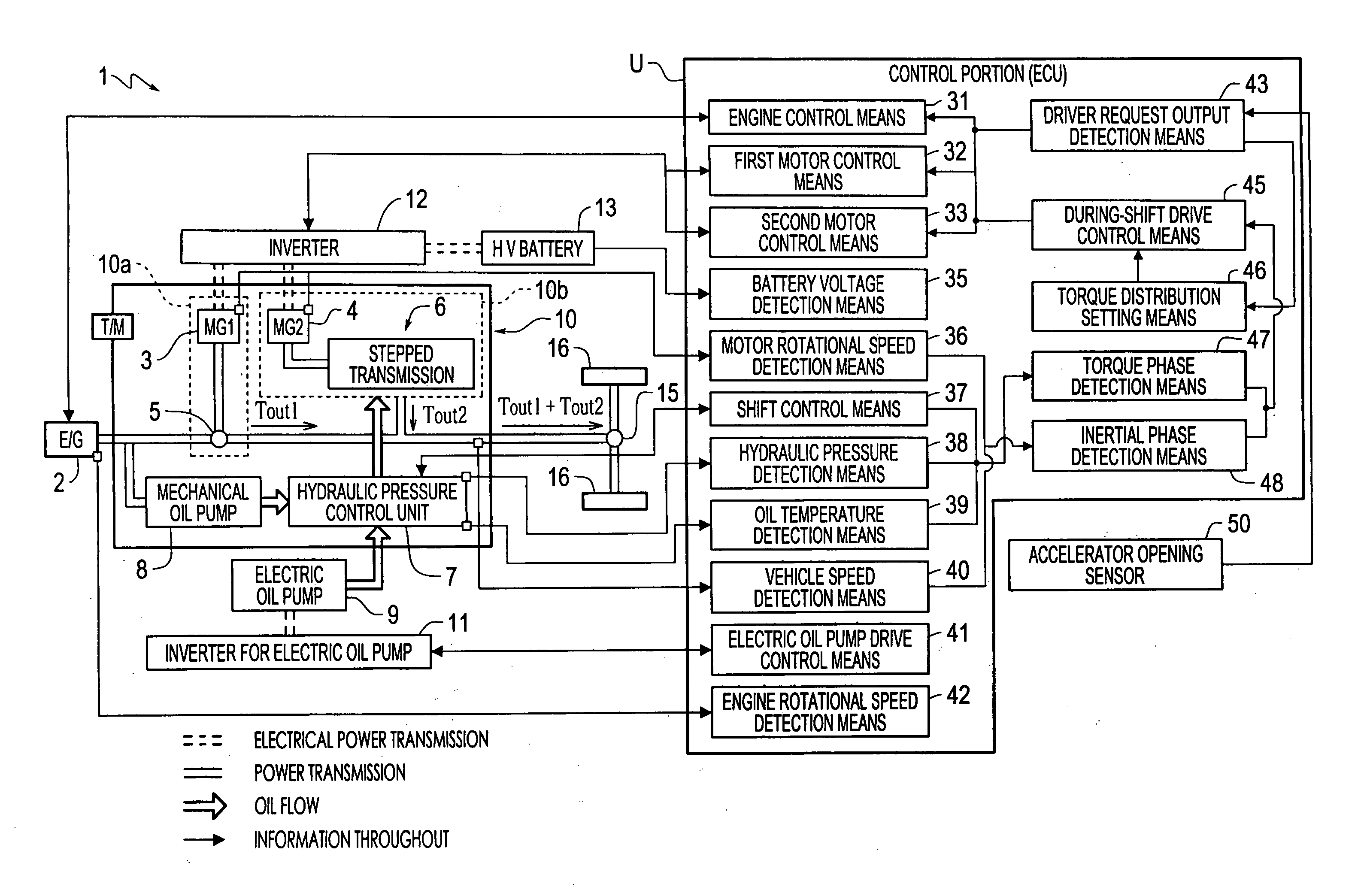
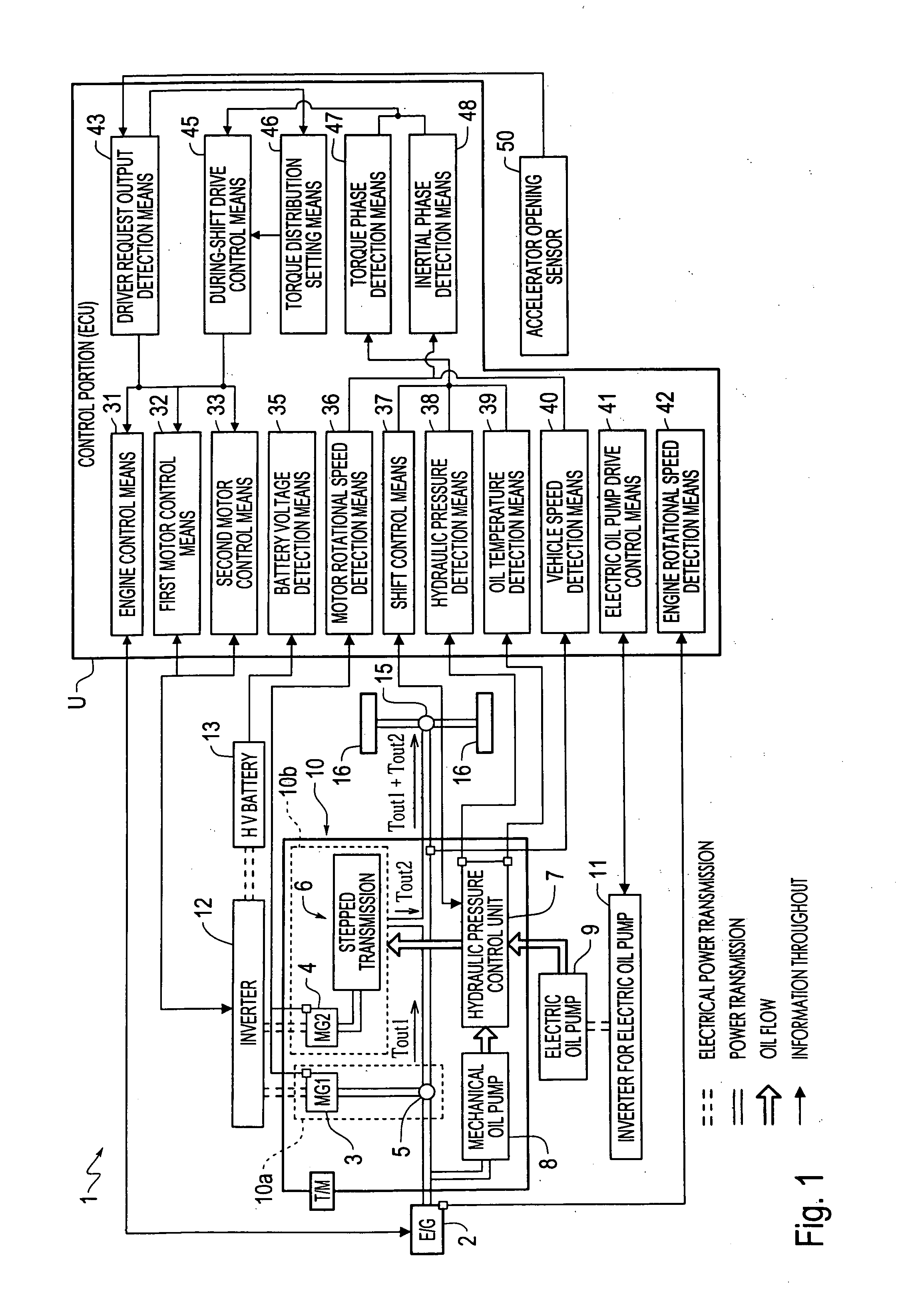
[0031] Hereinafter, an exemplary embodiment will be explained with reference to the drawings. As shown in FIG. 1, the hybrid vehicle is configured as a parallel hybrid of a two-motor split type. The hybrid vehicle is provided with an engine 2 capable of outputting a driving force, a transmission 10 connected to the engine 2, and drive wheels 16, 16 connected to the transmission 10 via a differential unit 15.

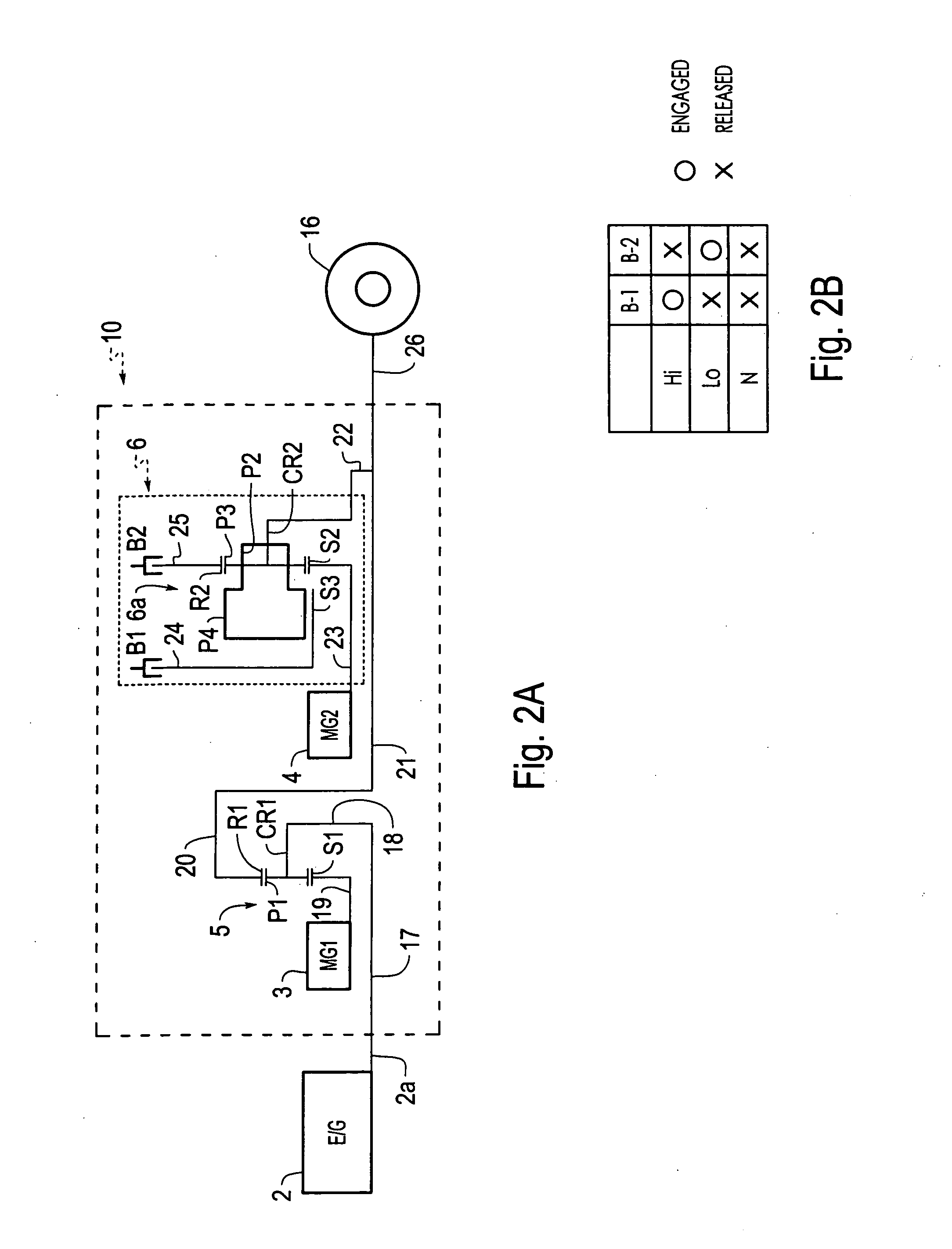
[0032] The transmission 10 is provided with a first drive unit 10a and a second drive unit 10b serving as a unit for outputting the driving force to the drive wheels 16, 16. The first drive unit 10a has a planetary gear 5, for power distribution, connected to the engine 2 via a damping apparatus (not shown) or the like, and a first motor 3 connected to the planetary gear 5. The first drive unit 10a is connected to a transmission shaft 21 via the planetary gear 5 for power distribution. Moreover, the second drive unit 10b has a second motor 4 and a stepped transmission 6 which is...


PUM


Abstract

A control system for a hybrid vehicle that is capable of absorbing an inertial force which is generated during shifting of a stepped transmission. During shift control of the stepped transmission by a shift control device and before the shift control is completed, a during-shift drive control element controls a driving force which is output from a second drive unit such that a total driving force which is output from first and second drive units to the drive wheels equals a driver request output. Further, the during-shift drive control elements executes control so as to reduce a difference between the total driving force output to a drive wheel and the driver request output based on a change in a transmission force of the stepped transmission caused by a switch-over between a first brake and a second brake. Moreover, in an inertial phase of the switch-over between the first brake and the second brake, the during-shift drive control means controls a driving force of a second motor so as to absorb an inertial force which is generated by change in a rotational speed of the second motor with respect to the rotational speed of the drive wheel.

Description

INCORPORATION BY REFERENCE [0001] The disclosure of Japanese Patent Application No. 2003-199463 filed on Jul. 18, 2003 including the specification, drawings and abstract is incorporated herein by reference in its entirety. BACKGROUND OF THE INVENTION [0002] 1. Field of Invention [0003] The invention relates to a control system for a hybrid vehicle which includes first and second drive units. The first drive unit has an engine, a first motor, and a planetary gear for power distribution. The second drive unit has a second motor and a stepped transmission which is interposed between the second motor and a transmission shaft and which transmits a driving force of the first and second drive units to drive wheels. More particularly, the invention relates to a control system for a hybrid vehicle, that is capable of outputting a driver request output to the drive wheels when the shifting of the stepped transmission is completed or while shifting is being executed. [0004] 2. Description of R...

Claims


Application Information

Patent Timeline
10 Feb 2005
Publication
US20050029023A1
IPC
B60K1/02; B60K6/445; B60K6/547; B60K17/04; B60L50/16; B60W10/00; B60W10/04; B60W10/06; B60W10/08; B60W10/10; B60W10/11; B60W10/115; B60W20/00; F02D29/02; F16H3/72; F16H59/14; F16H59/42; F16H59/44; F16H59/72; F16H61/04; F16H61/06; F16H61/68; F16H61/684; F16H61/686; F16H63/40; F16H63/50
CPC
B60K1/02; Y02T10/6239; B60K6/445; B60L2240/486; B60W10/06; B60W10/08; B60W10/10; B60W20/00
Inventors
TAKAMI, SHIGEKI; MIURA, KIYOTOMO