Expansion foam cavity filler and method

a filler and foam technology, applied in the field of expansion foam cavity filler and method, can solve the problem that polyethylene has almost no stretch, and achieve the effect of reducing vibration, noise, or fumes

Inactive Publication Date: 2005-02-10
RUST HENRY C
View PDF9 Cites 21 Cited by
  • Summary
  • Abstract
  • Description
  • Claims
  • Application Information

AI Technical Summary

Benefits of technology

[0018] The present invention provides for a cavity filler created by self-expanding plastic or elastomer foam contained in a flexible pouch. The pouch is placed into a cavity where it expands to fill up the cavity so as to reduce vibrations, noise, or fumes from entering or being transmitted through a vehicle, a vessel such as a ship or boat, a mobile or modular home, a building, machinery, or equipment. In the preferred embodiment of the present invention, the plastic or elastomeric foam is self curing so the cavity filler sets in the shape constrained by the pouch which is contained and constrained within the cavity.
[0019] Latex, vinyl, various rubber compounds, and urethane can be elastomeric, and as such, thin sheets made from these materials generate almost no noise when exposed to wind, movement, vibration, sound, or other mechanical actions. Prior art pouches were made of relatively noisy material such as high density polyethylene. A cavity filling pouch that does not generate noise is very desirable for applications in vehicles particularly in the automotive field as noise reduction in body panels is a critical goal. A thin pouch, made of elastic sheet material less than 10 thousandths of an inch thick will conform to required shapes within a panel. An elastomeric pouch will allow for expansion to fill around obstructions such as corners as the pouch can stretch. Prior art pouches of polyethylene were flexible, but the material polyethylene has almost no stretch, therefore has limitations in applications where complete filling of a cavity having irregular shapes and tight corners is desired.

Problems solved by technology

Prior art pouches of polyethylene were flexible, but the material polyethylene has almost no stretch, therefore has limitations in applications where complete filling of a cavity having irregular shapes and tight corners is desired.

Method used


Image

  • Expansion foam cavity filler and method
  • Expansion foam cavity filler and method
  • Expansion foam cavity filler and method

Examples


Embodiment Construction

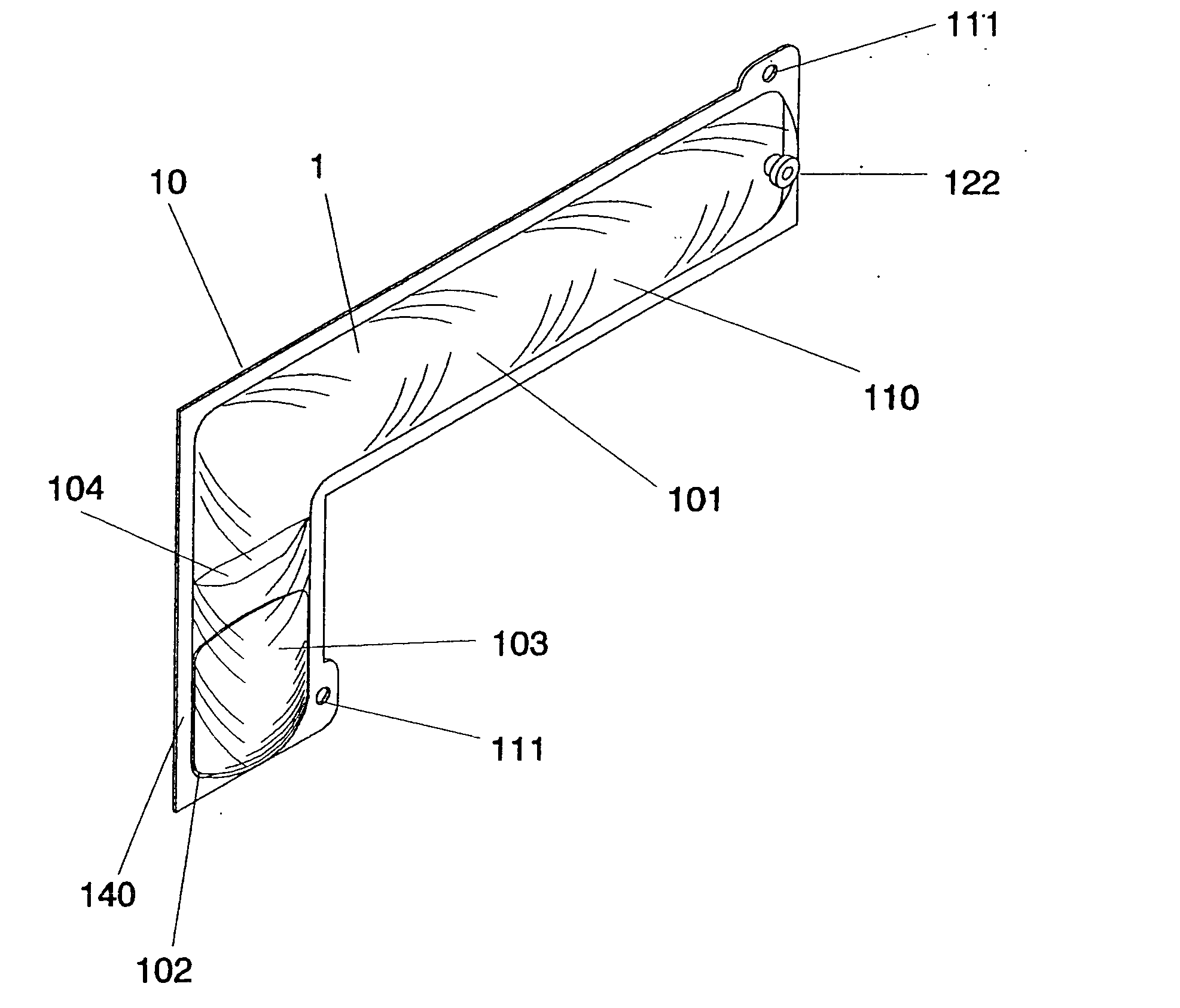
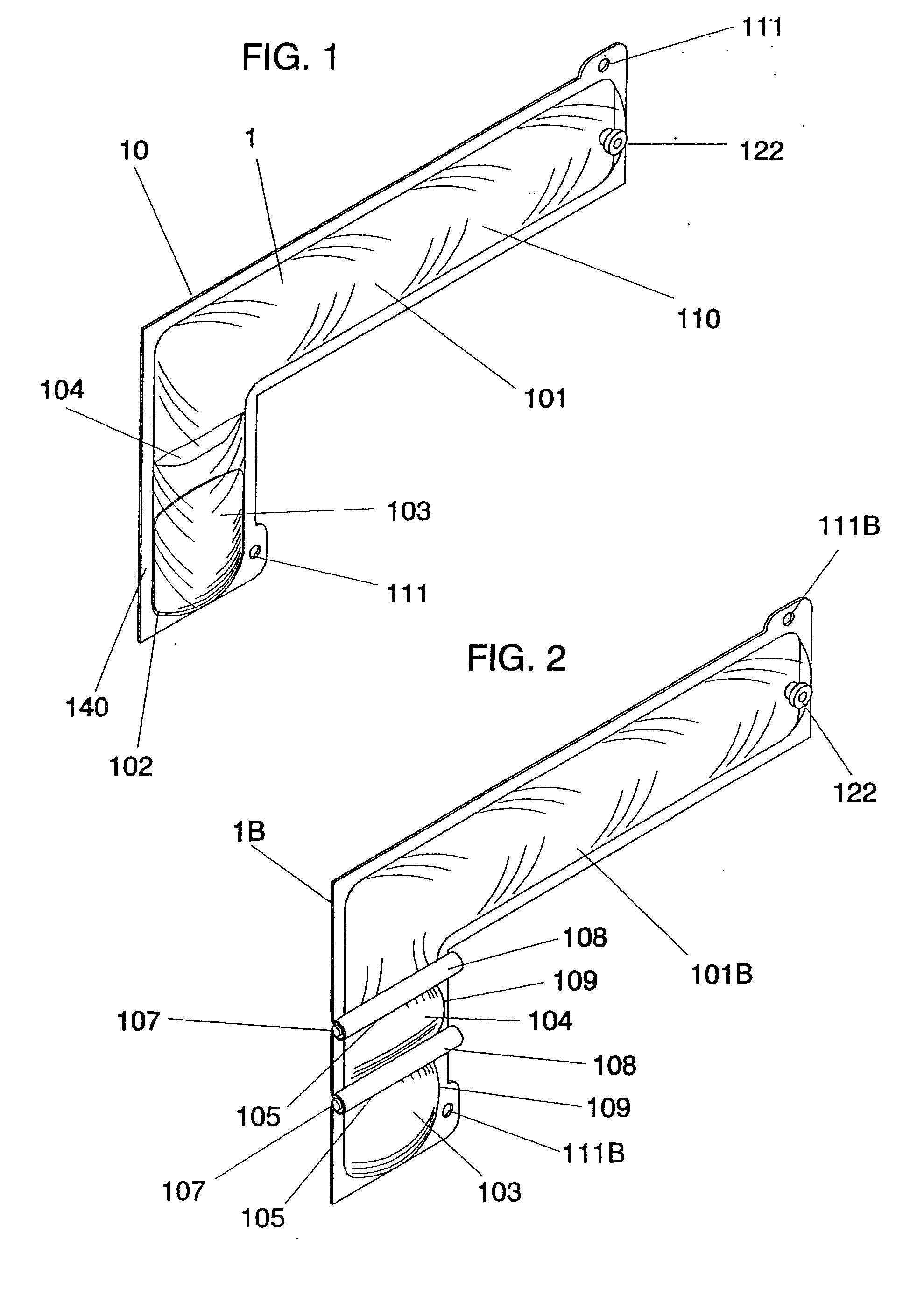
[0028] Referring to FIG. 1, in the preferred embodiment of the present invention, a cavity filler, an outer pouch 101, which is a flexible pouch, is fabricated in a given shape as desired for an intended application. The outer pouch 101 contains a first foam component 104. The outer pouch 101 may be composed of different types of material which affects characteristics such as, but not limited to, flexibility, stretch, density, toughness, strength, and adhesion of contents within the outer pouch 101 to the outer pouch 101.

[0029] The outer pouch 101 can be made from sheets of urethane in a thickness range from 1 thousandth to 10 thousands of an inch. Urethane provides a material that is very quiet in applications where the outer pouch 101 can be exposed to wind or other movement. This characteristic is particularly advantageous in vehicle applications and is ideal for automotive applications. A thickness of 3-4 thousandths of an inch appears to be ideal. FIGS. 6B and 6C show how the ...


PUM

PropertyMeasurementUnit
densityaaaaaaaaaa
densityaaaaaaaaaa
densityaaaaaaaaaa

Abstract

A plastic or elastomeric foam cavity filler, useable for filling of cavities such as are found in vehicles, ships, boats, mobile or modular homes, buildings, machinery, and equipment comprises a flexible pouch containing at least one material suitable for chemical or thermal activation which, upon activation of the material, the flexible pouch is placed in a cavity. The material expands the pouch to fit the cavity in which it was placed, restricting the entrance of, or transmission through, of noise, vibration, or fumes. When more than one foam component material is used, the component materials are separated within the flexible pouch. Among the means of separation are a pouch within the flexible pouch or barriers forming separate compartments in the pouch.

Description

CROSS REFERENCE TO RELATED APPLICATIONS [0001] None STATEMENT AS TO RIGHTS TO INVENTION MADE UNDER FEDERALLY SPONSORED RESEARCH AND DEVELOPMENT [0002] Not Applicable BACKGROUND OD THE INVENTION [0003] 1. Field of the Invention [0004] This invention relates to the use of a chemically or heat activated high expansion foam within a pouch to fill a cavity in motor vehicles, boats, ships, campers, mobile or modular homes, home appliances, buildings, machinery, and equipment. The pouch is a containment pouch that may be composed of a suitable material, or coated, so it adheres to a surface adjacent to the cavity. [0005] 2. Background Information [0006] The construction of an automobile body results in many cavities of various sizes and shapes. Some of these cavities are currently filled with a material, such as a foam plastic, to prevent noise or fumes from entering into the passenger compartment or from one compartment to another. Foam plastic materials, as a filler, are also used to red...

Claims


Application Information

Patent Timeline
Patent Type & Authority Applications(United States)
IPC IPC(8): B65D81/32
CPCB65D81/3272
Inventor RUST, HENRY C.
Owner RUST HENRY C
Why Eureka
Try Eureka