Aircraft flap or slat drive system with redundant drives and shaft drive lines

a technology of shaft drive and drive system, which is applied in the direction of aircraft power plants, transportation and packaging, and actuating personally, etc., can solve the problems of complete loss of the entire functionality of the landing flap and slat system, undesirable and improper behavior of the apparatus, and local overload of the arrangement, so as to maintain at least a partial operability and functionality of the overall apparatus, no and loss of the functionality of the apparatus

a technology of shaft drive and drive system, which is applied in the direction of aircraft power plants, transportation and packaging, and actuating personally, etc., can solve the problems of complete loss of the entire functionality of the landing flap and slat system, undesirable and improper behavior of the apparatus, and local overload of the arrangement, so as to maintain at least a partial operability and functionality of the overall apparatus, no and loss of the functionality of the apparatus

US20050029407A1Active Publication Date: 2005-02-10AIRBUS OPERATIONS GMBH

Image

  • Aircraft flap or slat drive system with redundant drives and shaft drive lines
  • Aircraft flap or slat drive system with redundant drives and shaft drive lines

Examples


Embodiment Construction

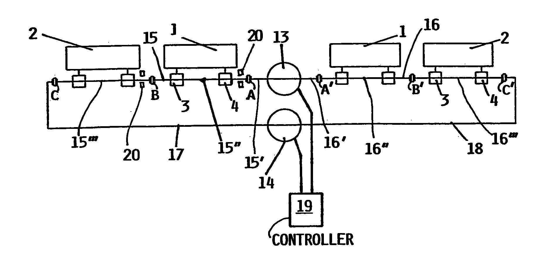
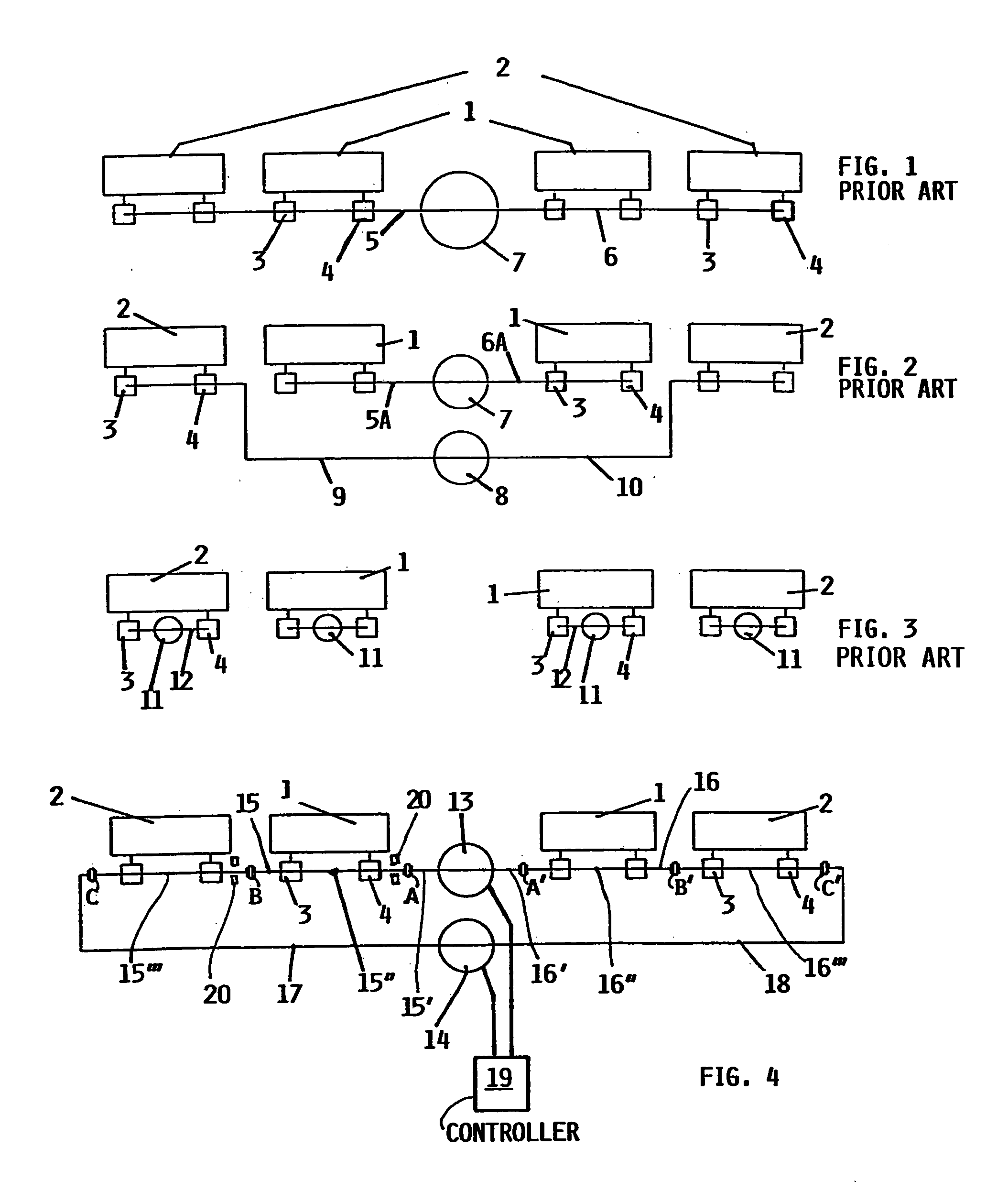
[0023] The conventional systems according to FIGS. 1, 2 and 3 have been described above. The inventive flap or slat drive apparatus according to FIG. 4 is based on some of the same conventional elements as the above described prior art systems. For example, the inventive apparatus according to FIG. 4, in this example embodiment, is for selectively driving or actuating left and right inboard lift enhancing elements 1, and left and right outboard lift enhancing elements 2, which may each be a trailing edge landing flap or a leading edge slat provided on the left and right wings of an aircraft. The final drive or actuation of the lift enhancing elements 1 and 2 is achieved by two actuator mechanisms 3, 4 connected to each one of the lift enhancing elements 1 or 2. The actuator mechanisms 3, 4 can have any conventionally known construction and operation, but basically convert a rotational input drive motion to a translational or deflecting output drive motion that is applied to the resp...


PUM


Abstract

An aircraft flap (or slat) drive apparatus includes first and second centralized drive units that respectively rotationally drive first and second drive lines in both wings. The first drive line includes shaft segments connected end-to-end by selectively engageable separating devices. The outboard ends of the first and second drive lines are coupled through one of the separating devices, in each wing. At least one actuator mechanism connects each flap to a respective shaft segment of the first drive line, and converts the drive line rotational motion to a flap translational motion. If a component breaks, jams, or otherwise fails, it is isolated by disengaging the two adjacent separating devices with the faulty component therebetween, so that the rest of the apparatus remains functional. Each one or both of the drive units can drive one or more or all of the flaps through the interconnected first and second drive lines.

Description

PRIORITY CLAIM [0001] This application is based on and claims the priority under 35 U.S.C. ยง119 of German Patent Application 103 26 799.9, filed on Jun. 13, 2003, the entire disclosure of which is incorporated herein by reference. FIELD OF THE INVENTION [0002] The invention relates to an apparatus for actuating lift enhancing elements, e.g. trailing edge flaps and / or leading edge slats, on the lifting wings of an aircraft, using at least one centralized drive unit that drives at least one rotational shaft drive line, which in turn drives actuator mechanisms, that convert the rotational motion of the shaft drive line into a translational motion of the lift enhancing elements. BACKGROUND INFORMATION [0003] The lift enhancing elements, including trailing edge landing flaps and leading edge slats, provided on the lifting wings of aircraft are conventionally operated or actuated by arrangements including a central drive unit, a respective rotational shaft drive line extending to the left...

Claims


Application Information

Patent Timeline
10 Feb 2005
Publication
US20050029407A1
IPC
B64C9/16; B64C13/24
CPC
B64C9/16; B64C13/24; Y02T50/44; B64D2045/001; B64D45/0005; Y02T50/40
Inventors
POHL, ULRICH; THOMAS, CARSTEN