Fluid stream feed device for mass transfer column

a technology of mass transfer column and feed device, which is applied in the direction of carburetor air, combustion air/fuel air treatment, and separation processes, etc., can solve the problems of increased turbulence and greater pressure drop

Inactive Publication Date: 2005-02-10
KOCH GLITSCH INC
View PDF11 Cites 30 Cited by
  • Summary
  • Abstract
  • Description
  • Claims
  • Application Information

AI Technical Summary

Benefits of technology

[0006] In one aspect, the present invention is directed to a mass transfer column of the type having an external upright shell defining an open internal region within the shell; a feed nozzle surrounding an opening in the shell and extending outwardly from the shell in radial alignment with a vertical center axis of said shell, the feed nozzle having a notional radially extending center vertical plane, the opening having a preselected diameter and defining an inlet passage; and a feed device within the open internal region and positioned in relation to the opening in the shell to deflect and redirect the vapor or mixed phase stream entering the open internal region through the feed nozzle. The feed device has an inner wall that is spaced inwardly from the shell and an annular passageway that is defined by the spacing between the inner wall and the shell and is in fluid flow communication with the inlet passage. A pair of upright deflecting surfaces extends from the inner wall of the feed device toward the opening surrounded by the feed nozzle. Each of the deflecting surfaces has an outer end positioned closer to the shell and an opposed inner end positioned closer to the inner wall of the feed device. The deflecting surfaces are preferably generally symmetrically oriented on opposite sides of the center vertical plane of the feed nozzle with the outer ends of the deflecting surfaces being positioned closer to the center vertical plane than the inner ends of the deflecting surfaces. The deflecting surfaces divide the entering vapor or mixed phase stream into roughly equal streams that flow in opposite circumferential directions in the annular passageway. The inner ends of the deflecting surfaces are also preferably secured to the inner wall of the feed device to transfer the force exerted on the deflecting surfaces by the vapor or mixed phase stream to the inner wall. In accordance with the present invention, at least a first pair of turning vanes are positioned on opposite sides of the center vertical plane of the feed nozzle and are circumferentially spaced from the deflecting surfaces in the annular passageway. The turning vanes each have a radially outer end and an opposed radially inner end with the outer end being located closer to the center vertical plane than the inner end. The turning vanes are preferably generally symmetrically oriented on said opposite sides of the center vertical plane. The turning vanes and deflecting surfaces divide the inlet passage into subpassages, with the total flow of the vapor or mixed phase stream being split among the subpassages. As a result, only a portion of the vapor or mixed phase stream entering the annular passageway of the feed device impacts against the inner wall. Additional pairs of turning vanes may be employed to further reduce the amount of the vapor or mixed phase stream that impacts against the inner wall of the feed device. The invention may also be employed with a second nozzle positioned diametrically opposite from the first nozzle.

Problems solved by technology

The ability of the turning vanes to reduce pressure drop was unexpected because it was previously believed that the turning vanes would partially obstruct the opening in the feed nozzle and cause greater pressure drop and increased turbulence.

Method used


Image

  • Fluid stream feed device for mass transfer column
  • Fluid stream feed device for mass transfer column
  • Fluid stream feed device for mass transfer column

Examples


Embodiment Construction

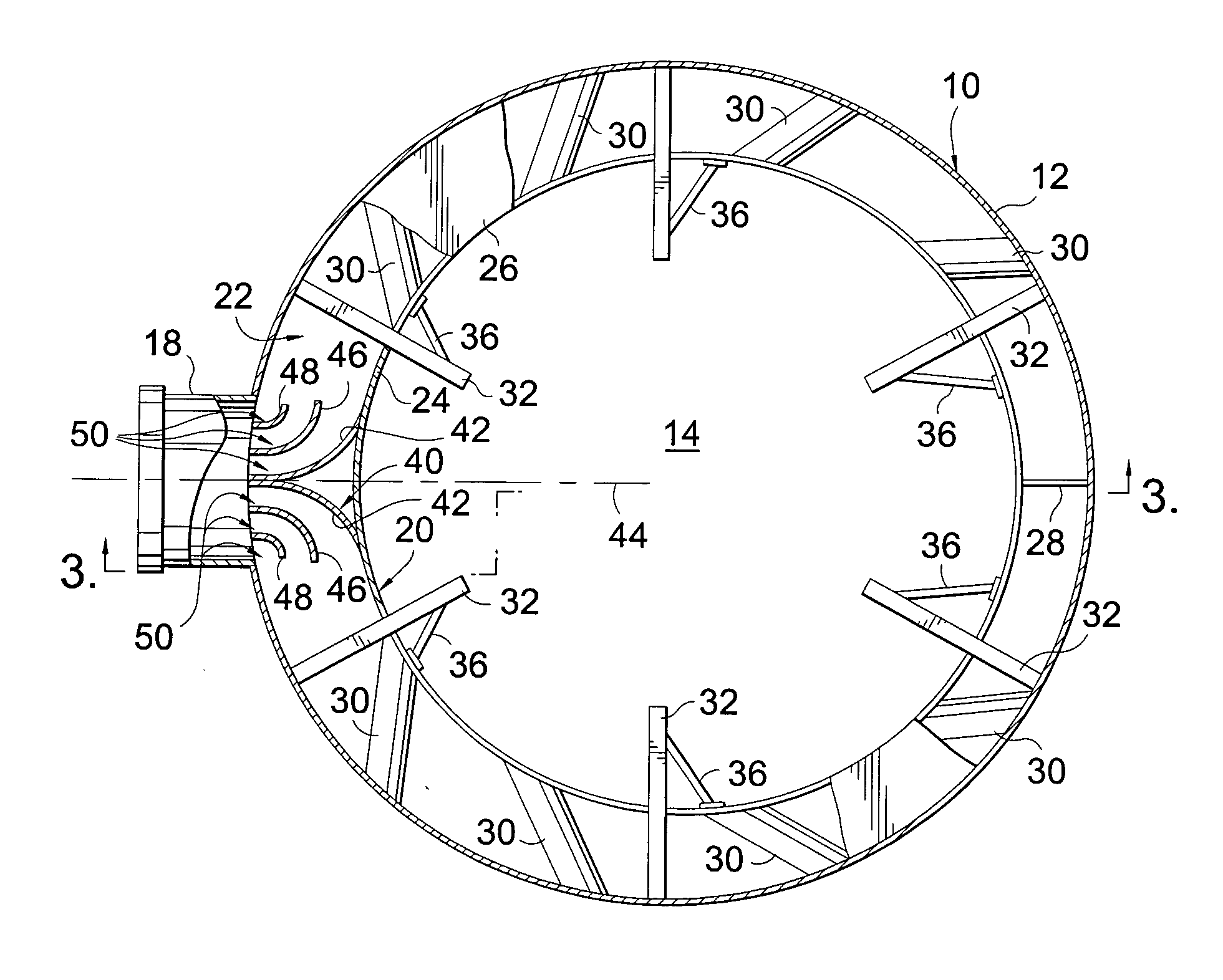
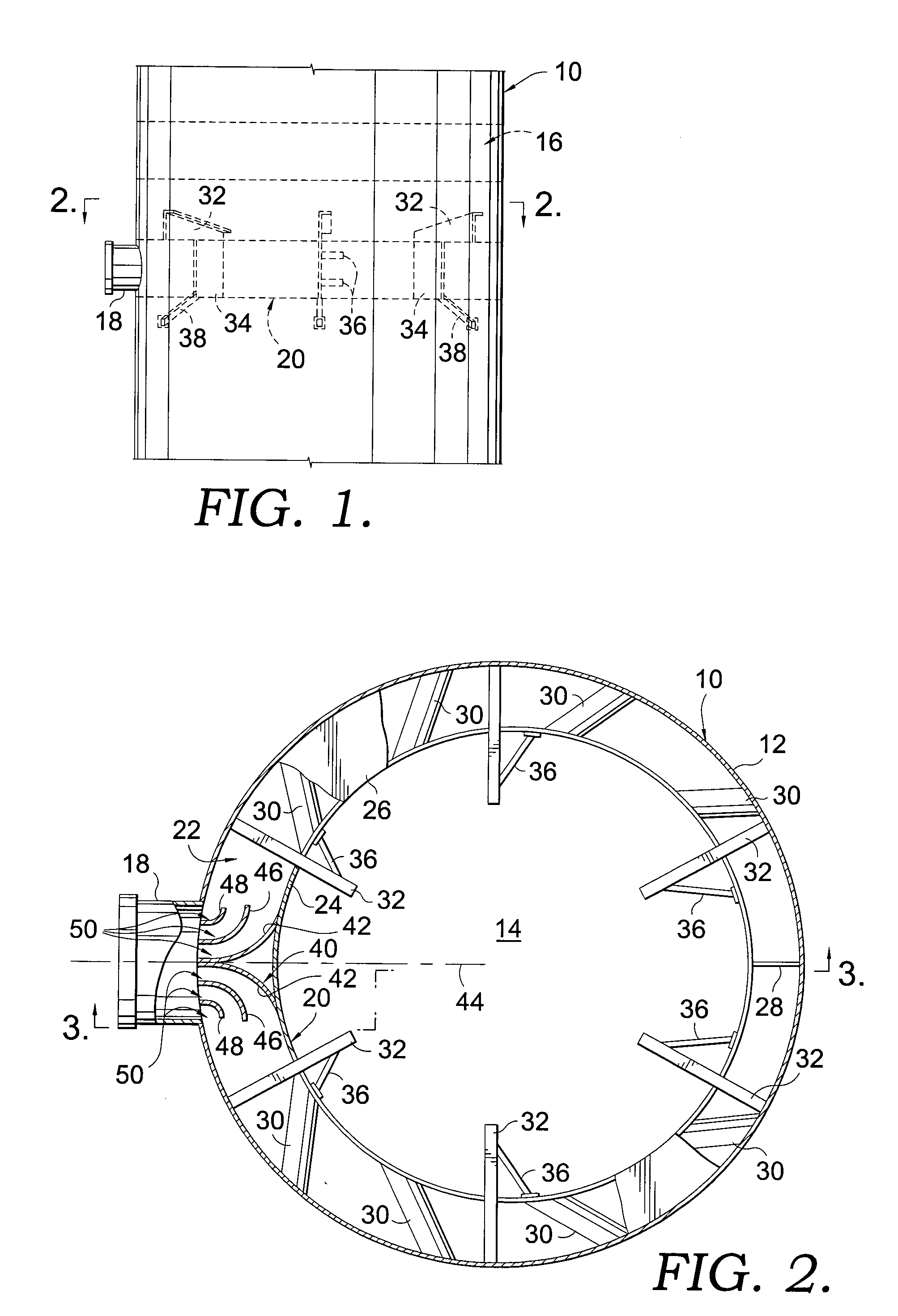
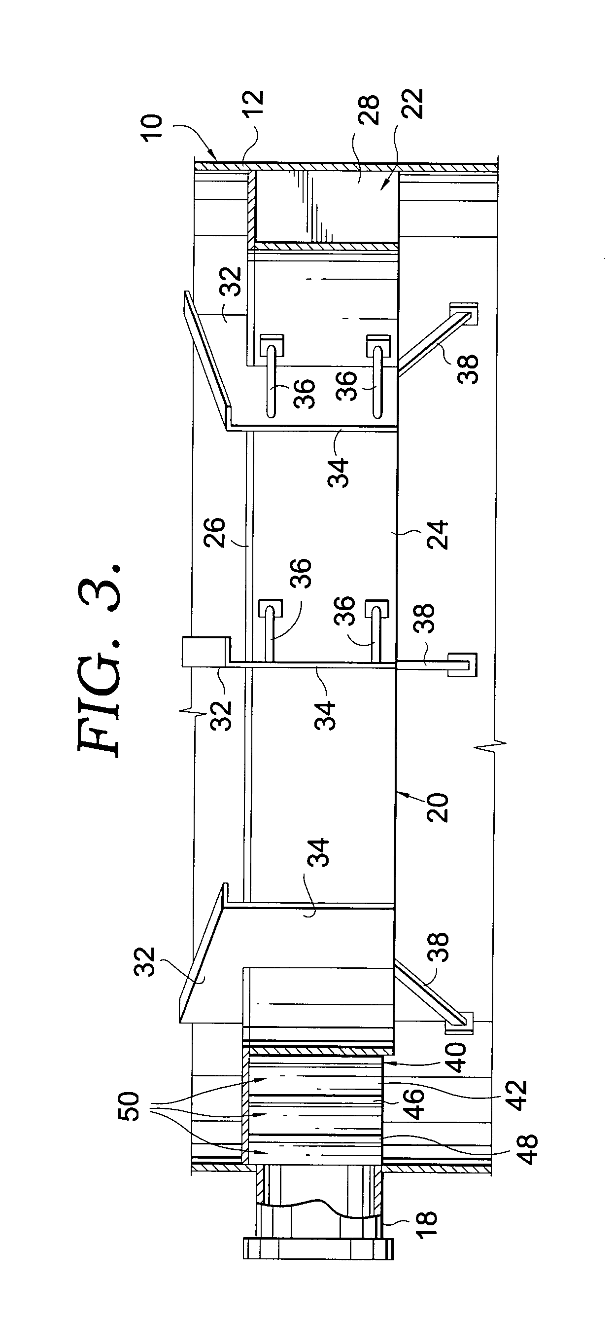
[0015] Turning now to the drawings in greater detail and initially to FIGS. 1-4, a column constructed in accordance with a first embodiment of the present invention is represented broadly by the numeral 10. Column 10 comprises a cylindrical exterior shell 12 and presents an open internal region 14 in which mass transfer and / or heat exchange between fluid streams occurs. A common use of such columns is to effect mass transfer between one or more downwardly flowing liquid streams and one or more ascending vapor stream. Alternatively, the fluid stream can both be liquid streams or a gas stream and a liquid stream.

[0016] Column 10 includes a zone 16 (FIG. 1) in which mass transfer devices such as trays or packing are positioned to facilitate interaction between the fluid streams flowing through the open internal region 14 of the column 10. The packing can be random or structured packing and multiple zones of such packing can be provided.

[0017] The fluid streams are directed to the col...


PUM

PropertyMeasurementUnit
diameteraaaaaaaaaa
pressure dropaaaaaaaaaa
diameteraaaaaaaaaa

Abstract

A mass transfer column includes a feed device that is used to de-entrain liquid and more uniformly distribute vapor across a horizontal cross section of the column after a vapor or mixed phase stream has been directed into the column through a radially oriented feed nozzle. The feed device includes an annular passageway formed in the spacing between the column shell and an inner wall spaced inwardly from the shell. A deflector with oppositely directed deflecting surfaces is positioned at an inlet from the feed nozzle to the annular passageway and splits the vapor or mixed phase stream into two roughly equal streams that flow in opposite circumferential directions in the annular passageway. At least one pair of turning vanes is spaced on opposite sides of the deflecting surfaces in the annular passageway to create subpassages through which the vapor or mixed phase stream flows. The subpassages reduce the amount of vapor or mixed phase stream flow that impacts against the inner wall of the feed device at the inlet. The turning vanes unexpectedly reduce the pressure drop that occurs as the vapor or mixed phase stream is redirected from its radial entry direction to the circumferential direction in the annular passageway. By reducing the pressure drop, improvements in product yield and vapor distribution can be achieved.

Description

BACKGROUND OF THE INVENTION [0001] This invention relates generally to mass transfer columns and, more particularly, to an apparatus and method for feeding a vapor or a vapor and liquid mixed phase stream into the column in a manner that allows a more uniform distribution of the vapor or mixed phase stream within the column. As used herein, the term “mixed phase stream” is intended to refer to a stream containing both vapor and liquid. [0002] Mass transfer columns, including heat exchange columns, typically include an upright shell and a plurality of zones within the shell where contacting devices such as random or structured packing and / or horizontally disposed trays are used to facilitate mass or heat transfer between fluid streams flowing within the column. The fluid streams are normally descending liquid streams and ascending vapor stream, but other combinations of fluid streams are possible. As the fluid streams spread over the surface of the packing or tray, the surface area o...

Claims


Application Information

Patent Timeline
Patent Type & Authority Applications(United States)
IPC IPC(8): B01D3/00
CPCB01D3/008
Inventor LAIRD, DANA G.SCHNEPPER, CAROL A.ENDER, CHRISTOPH
Owner KOCH GLITSCH INC
Why Eureka
Try Eureka