State-based remote control system

a remote control system and state technology, applied in transmission systems, automatic controllers, transmission systems, etc., can solve the problems of inability to detect or monitor the state of a particular electronic device, relatively high device cost, undesirable effect, etc., and achieve the effect of efficient and simple operation

Inactive Publication Date: 2005-02-10
LOGITECH EURO SA +2
View PDF99 Cites 42 Cited by
  • Summary
  • Abstract
  • Description
  • Claims
  • Application Information

AI Technical Summary

Benefits of technology

[0013] In view of the foregoing disadvantages inherent in the known types of remote controls now present in the prior art, the present invention provides a new state-based remote control system construction wherein the same can be utilized for providing efficient and simple operation of a plurality of electronic devices as a coordinated system based upon an overall task.
[0019] A second object is to provide a state-based remote control system for providing efficient and simple operation of a plurality of electronic devices as a coordinated system based upon an overall task.
[0021] An additional object is to provide a state-based remote control system that allows for the simple operation of a plurality of electronic devices based upon an overall “task” instead of specific controls for specific electronic devices.
[0022] A further object is to provide a state-based remote control system that is simple and easy to utilize for the average consumer.
[0023] Another object is to provide a state-based remote control system that does not require significant programming prior to usage.
[0024] An additional object is to provide a state-based remote control system that is affordable.

Problems solved by technology

The main problem with conventional universal remote controls is that they are unable to detect or monitor the state of a particular electronic device.
Another problem with conventional universal remote controls is that when a preprogrammed macro is executed, an undesirable effect can occur wherein electronic devices that are desired to be turned on are actually turned off.
These devices are relatively expensive and again difficult to utilize for the average consumer.
The main problem with conventional remote control devices is that they are typically unable to know the particular “state” of an electronic device they are to control, particularly universal remote controls.
A further problem with conventional remote controls that do allow for advanced configuration thereof to compensate for the various states of the electronic device is that they are often times difficult for the average consumer to utilize.
Another problem with conventional remote control devices is that they force consumers to view their electronic devices “individually” (i.e. turn television on, turn stereo on, switch audio input on stereo to television) rather than in broad “tasks” (e.g. watch television).
While these devices may be suitable for the particular purpose to which they address, they are not as suitable for providing efficient and simple operation of a plurality of electronic devices as a coordinated system based upon an overall task.
Conventional universal remote controls are typically programmed to operate electronic devices “individually” or are difficult to configure to automated control of a plurality of electronic devices.

Method used


Image

  • State-based remote control system
  • State-based remote control system
  • State-based remote control system

Examples


Embodiment Construction

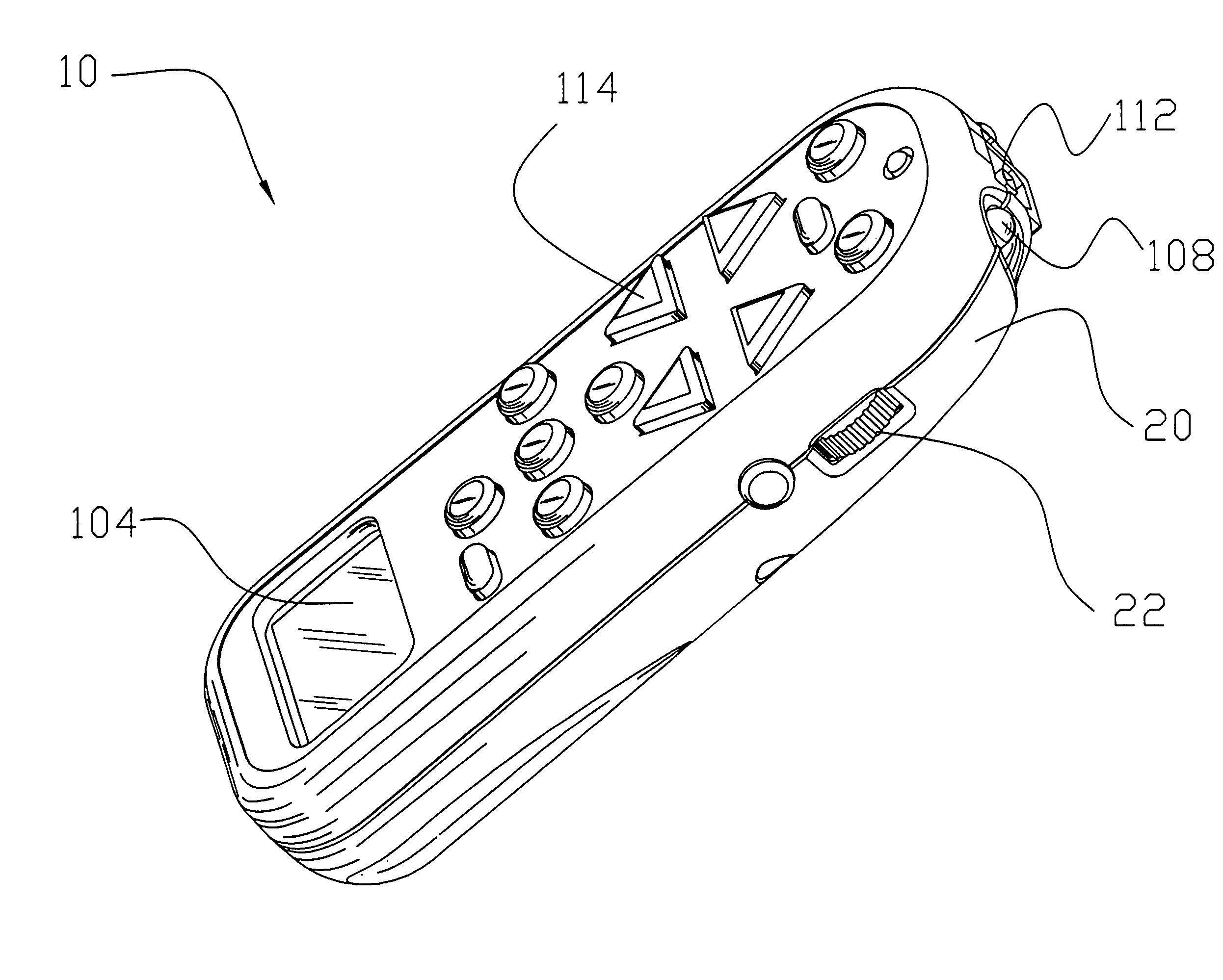
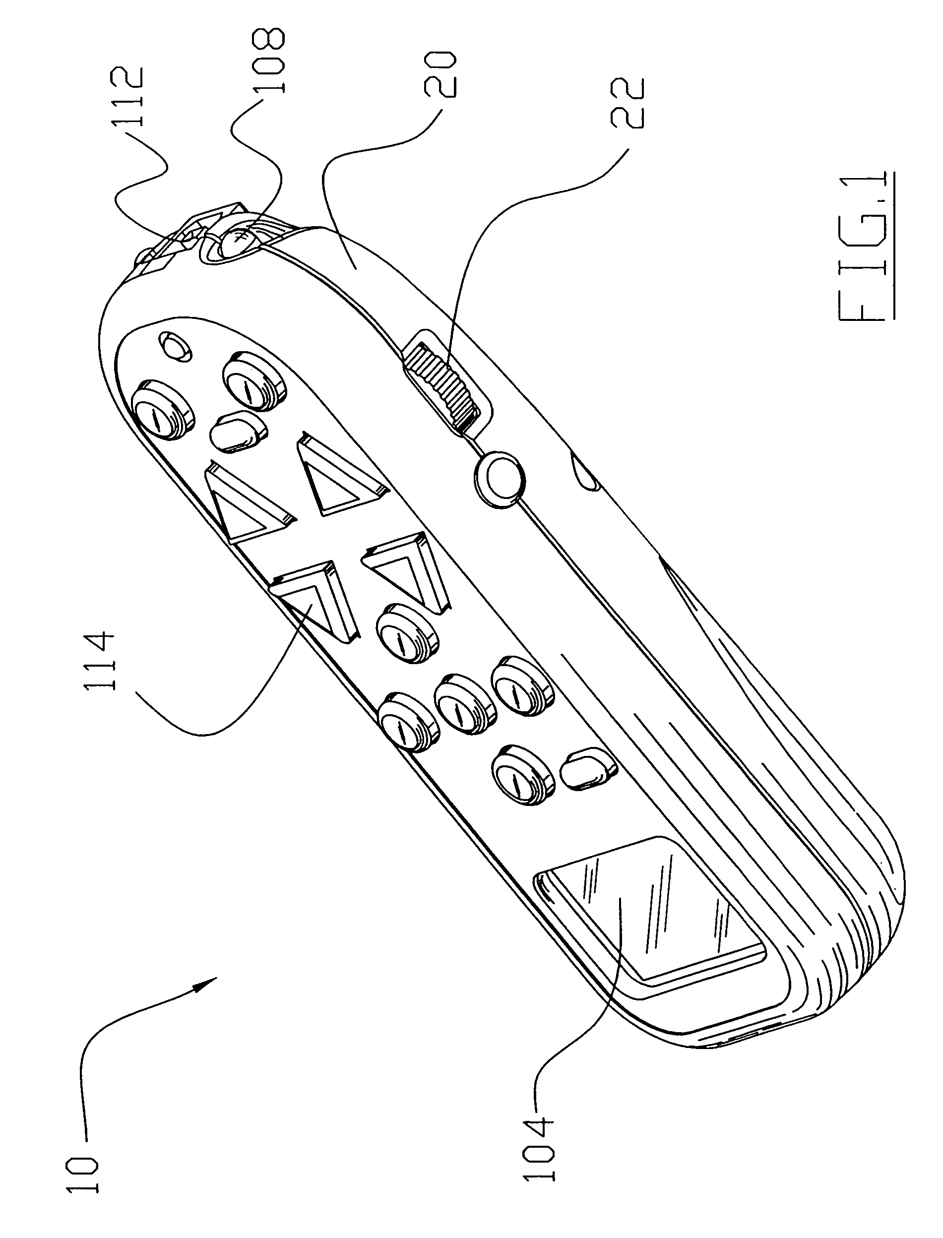
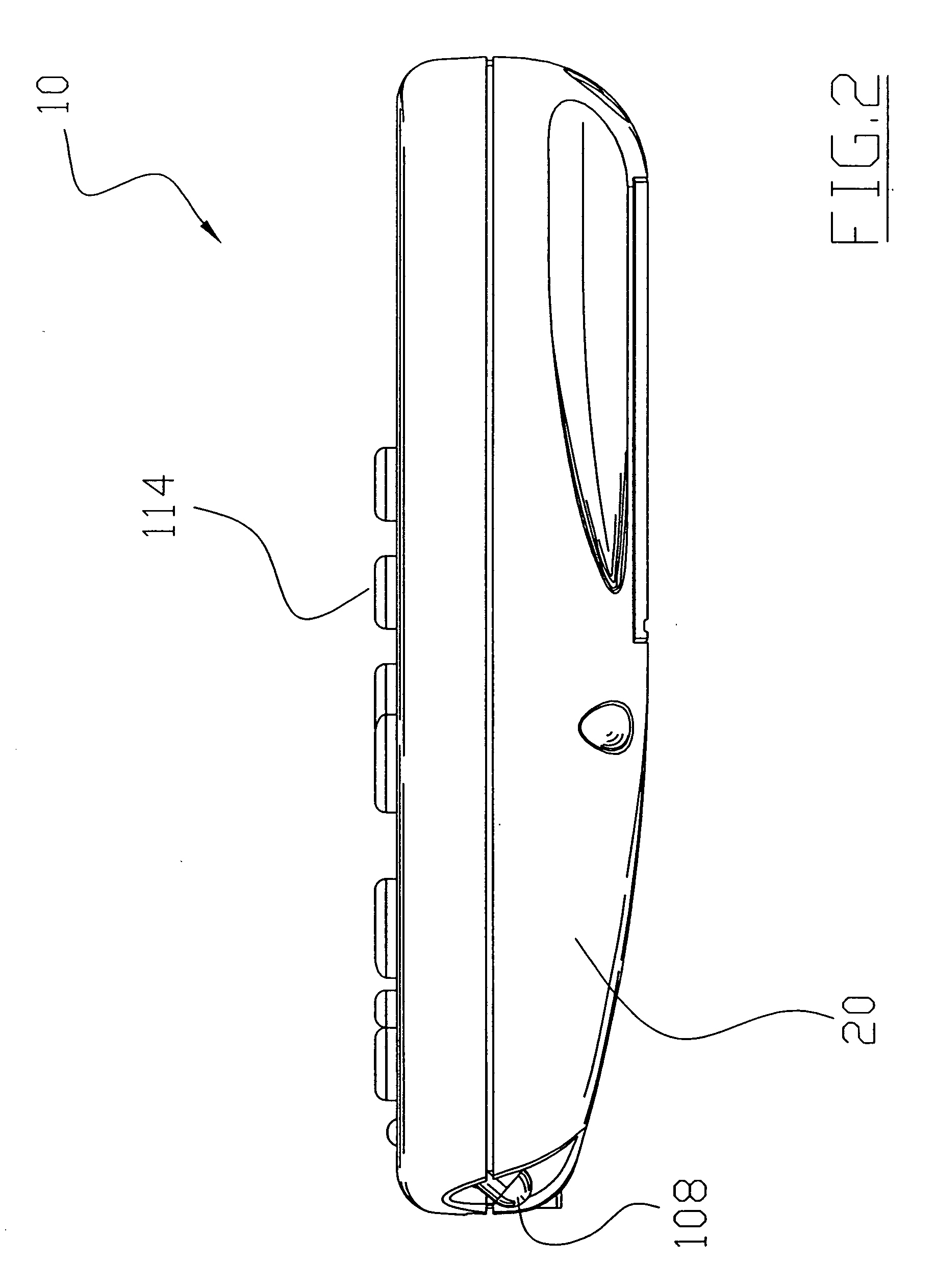
[0039] Turning now descriptively to the drawings, in which similar reference characters denote similar elements throughout the several views, FIGS. 1 through 11 illustrate a state-based remote control system 10, which comprises a housing 20, a keypad 114 in communication with an electronic system 100 contained within the housing 20, and a communication device 108 in communication with the electronic system 100 for communicating with external electronic devices 12. The electronic system 100 constantly monitors the buttons of the keypad 114 and other switches selected by a user to determine the state of all external electronic devices 12 that are to be controlled. When the user selects a task (e.g. watch television), the electronic system 100 automatically determines the actions required to achieve the desired task based upon the current state of the external electronic devices 12. After the task has been fulfilled, the electronic system 100 updates the data to reflect the modified st...


PUM


Abstract

A state-based remote control system for providing efficient and simple operation of a plurality of electronic devices as a coordinated system based upon an overall task. The state-based remote control system includes a housing, a keypad in communication with an electronic system contained within the housing, and a communication device in communication with the electronic system for communicating with external electronic devices. The electronic system monitors the buttons selected by a user to determine the state of all external electronic devices that are to be controlled. When the user selects a task (e.g. watch television), the electronic system automatically determines the actions required to achieve the desired task based upon the current state of the external electronic devices. After the task has been fulfilled, the electronic system updates the data to reflect the modified state of the external electronic devices.

Description

CROSS-REFERENCE TO RELATED U.S. PROVISIONAL PATENT APPLICATIONS [0001] I hereby claim benefit under Title 35, United States Code, Section 119(e) of U.S. provisional patent application Ser. No. 60 / 189,487 filed Mar. 15, 2000, and U.S. provisional patent application Ser. No. 60 / 253,727 filed Nov. 29, 2000. This application is a continuation of the application Ser. Nos. 60 / 189,487 and 60 / 253,727. The application Ser. Nos. 60 / 189,487 and 60 / 253,727 are currently pending. The application Ser. Nos. 60 / 189,487 and 60 / 253,727 are hereby incorporated by reference into this patent application.BACKGROUND OF THE INVENTION [0002] 1. Field of the Invention [0003] The present invention relates generally to remote control devices and more specifically it relates to a state-based remote control system for providing efficient and simple operation of a plurality of electronic devices as a coordinated system based upon an overall task. [0004] 2. Description of the Prior Art [0005] Remote control device...

Claims


Application Information

Patent Timeline
Patent Type & Authority Applications(United States)
IPC IPC(8): G08C19/28
CPCG08C17/00G08C19/28G08C2201/21H04L12/282G08C2201/92H04L12/2814G08C2201/50
Inventor HARRIS, GLEN MCLEANHENRY, JUSTIN M.
Owner LOGITECH EURO SA
Why Eureka
Try Eureka