Low power telemetry system and method

a telemetry system and low power technology, applied in the field of telemetry systems, can solve the problems of excessive consumption of power and cannot be further optimized for very low power applications

Inactive Publication Date: 2005-02-10
GENERAL DYNAMICS MISSION SYST INC
View PDF22 Cites 34 Cited by
  • Summary
  • Abstract
  • Description
  • Claims
  • Application Information

AI Technical Summary

Benefits of technology

[0003] In a first aspect of this disclosure, a telemetry system is described. The system comprises a bus and a plurality of channels each coupled to the bus. A control subsystem (1) controls the channels so that each one presents to the bus, during a time period designated for the channel, a channel characteristic representative of a signal sampled by the channel, (2) interrogates in the analog domain each of the channels, during the time period designated for a channel, the characteristic presented by the channel, and (3) forms a signal representative of the characteristic presented by the channel during the designated time period.

Problems solved by technology

Conventional telemetry systems typically function in the digital domain, and consume excessive power because of the high clock rates incident to the use of digital circuitry, and the infrastructure needed to support digital domain processing.
Dissipated power in such systems is ultimately dominated by this digital infrastructure and, as such, cannot be further optimized for very low power applications, such as autonomous underwater surveillance, very large scale fixed systems, multi-line towed array systems, and other multiplexed sensor systems that are required to operate in “power limited” applications.
The channel impedance presented by the channel creates an impedance mismatch, which causes a modulated version of the pulse to be reflected back to a termination device coupled to one end of the bus.

Method used


Image

  • Low power telemetry system and method
  • Low power telemetry system and method
  • Low power telemetry system and method

Examples


Embodiment Construction

[0023] As utilized herein, terms such as “about” and “substantially” and “near” are intended to allow some leeway in mathematical exactness to account for tolerances that are acceptable in the trade. Accordingly, any deviations upward or downward from the value modified by the terms “about” or “substantially” or “near” in the range of 1% to 20% or less should be considered to be explicitly within the scope of the stated value.

[0024] The term “logic” refers to implementations in hardware, software, or combinations of hardware and software.

[0025] The term “packet” means a grouping of digital data and control elements which is switched and transmitted as a composite whole, wherein the data and control elements and possibly error control information are arranged in a specified format. The term “packet” includes a frame.

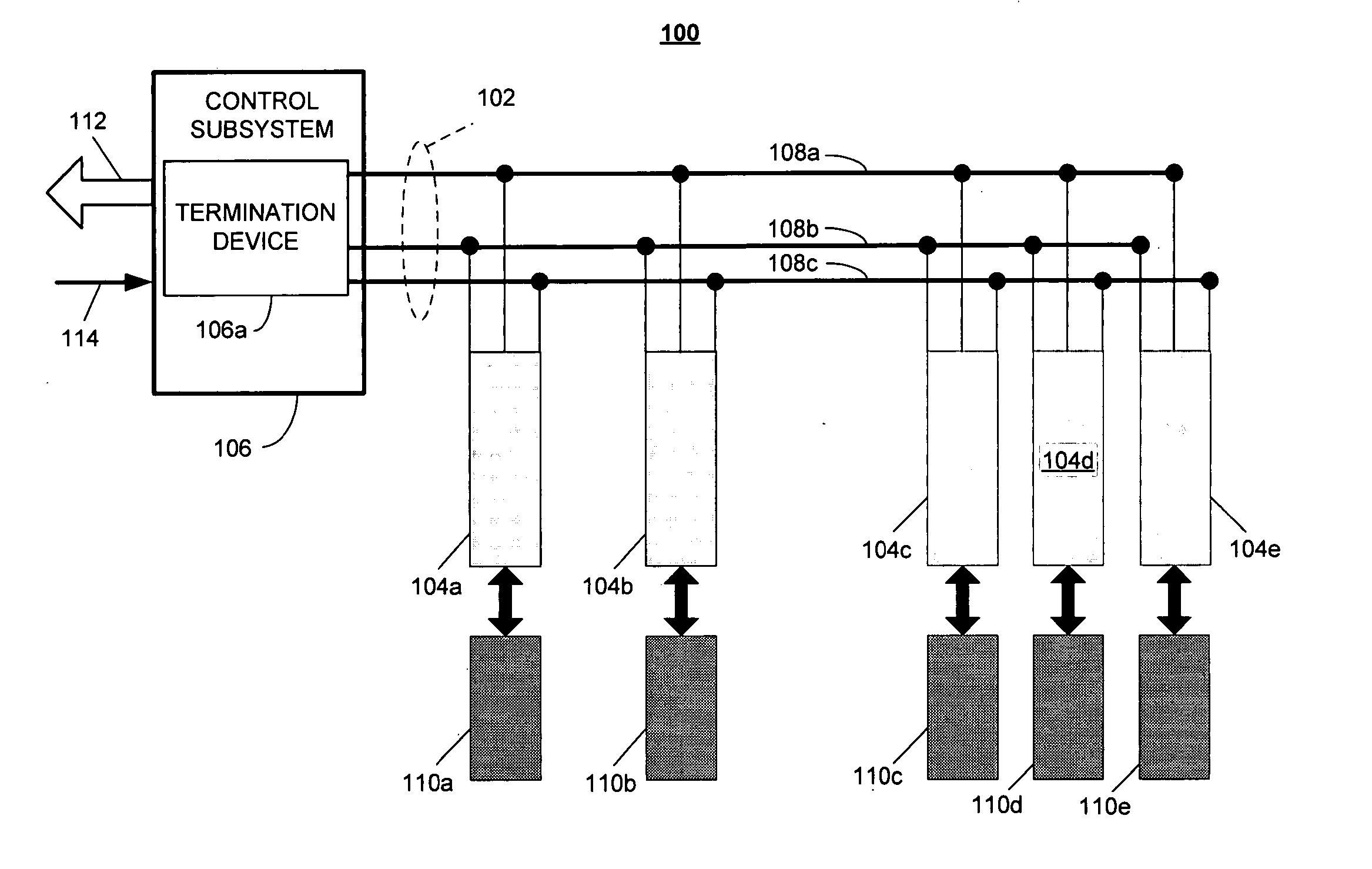
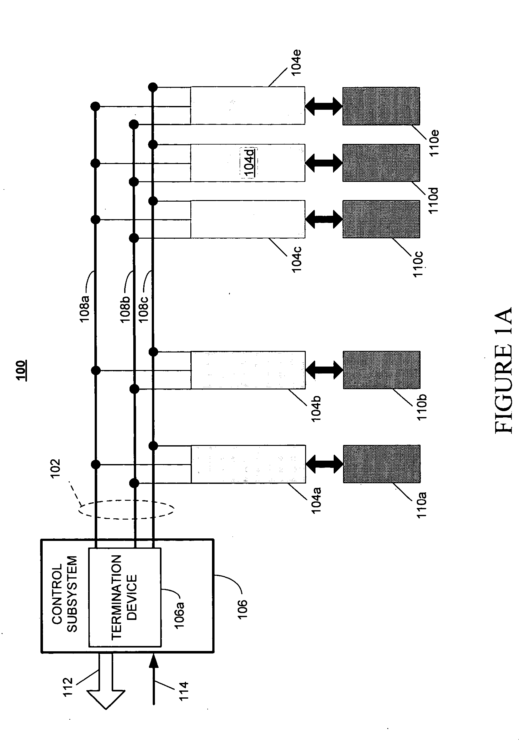
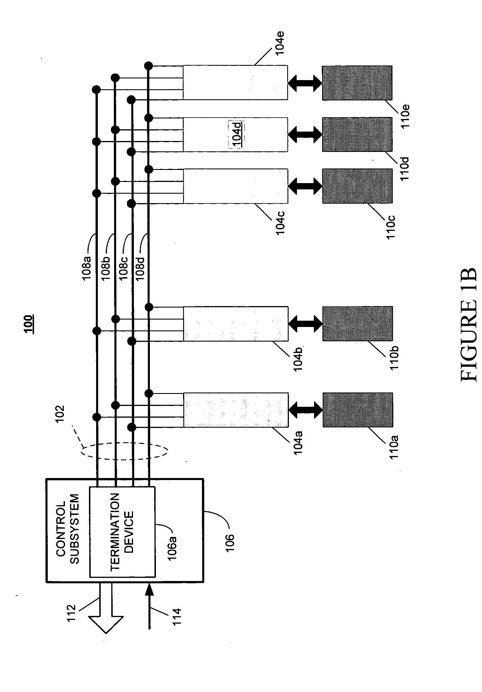
[0026]FIG. 1A illustrates one embodiment of a telemetry system 100 according to the invention. The system comprises a bus 102, and a plurality of channels 104a, 104b, ...


PUM


Abstract

A telemetry system is described in which a plurality of channels are coupled to a bus. A control subsystem controls the channels so that one of the channels presents to the bus during its designated time period a channel characteristic. The control subsystem interrogates in the analog domain each of the channels during its designated time period, and forms a signal representative of the channel characteristic. The control subsystem may combine one or more of the signals into a digital packet, and transmit the same over a network.

Description

1 FIELD OF THE INVENTION [0001] This invention relates to the field of telemetry systems, and, more specifically, to very low power time division multiplexed analog domain telemetry systems. 2 RELATED ART [0002] Conventional telemetry systems typically function in the digital domain, and consume excessive power because of the high clock rates incident to the use of digital circuitry, and the infrastructure needed to support digital domain processing. Dissipated power in such systems is ultimately dominated by this digital infrastructure and, as such, cannot be further optimized for very low power applications, such as autonomous underwater surveillance, very large scale fixed systems, multi-line towed array systems, and other multiplexed sensor systems that are required to operate in “power limited” applications. SUMMARY [0003] In a first aspect of this disclosure, a telemetry system is described. The system comprises a bus and a plurality of channels each coupled to the bus. A cont...

Claims


Application Information

Patent Timeline
Patent Type & Authority Applications(United States)
IPC IPC(8): H04Q9/00
CPCH04Q9/00H04Q2209/756H04Q2209/30
Inventor HOLT, MICHAEL D.
Owner GENERAL DYNAMICS MISSION SYST INC
Why Eureka
Try Eureka