Video processing apparatus, video processing method, and computer program

a video processing and video processing technology, applied in the field of video processing apparatus, video processing method, computer program, can solve the problems of not controlling the generation of motion blur, more frequent occurrence of motion blur, and inability to detect motion blur

Inactive Publication Date: 2005-02-10
SONY CORP
View PDF14 Cites 45 Cited by
  • Summary
  • Abstract
  • Description
  • Claims
  • Application Information

AI Technical Summary

Benefits of technology

The present invention thus controls the holding type display device such as the liquid-crystal display device in the display function thereof. The present invention controls the motion blur of a moving picture in the holding type display device such as the liquid-crystal display device.

Problems solved by technology

However, the liquid-crystal display device has a drawback that the occurrence of motion blur is more frequent than in the impulsive type display device when a moving picture is displayed.
It has been considered that the generation of motion blur in the liquid-crystal display device is caused by a slow response of the liquid crystal.
Even with the overdrive method in operation, the generation of motion blur is not controlled.
Currently, no effective method for controlling the motion blur is available in the liquid-crystal display device.
The liquid-crystal display device is not free from the above drawback.
However, this drawback affects not only the liquid-crystal display device, but also any type of display device that includes a plurality of display elements, each of which takes a predetermined time to-reach an output target level from the addressing of the target level, and is associated with at least a portion of a predetermined one of pixels forming a frame or a field.
The above-referenced drawback is a common problem of the holding type display device.

Method used


Image

  • Video processing apparatus, video processing method, and computer program
  • Video processing apparatus, video processing method, and computer program
  • Video processing apparatus, video processing method, and computer program

Examples


Embodiment Construction

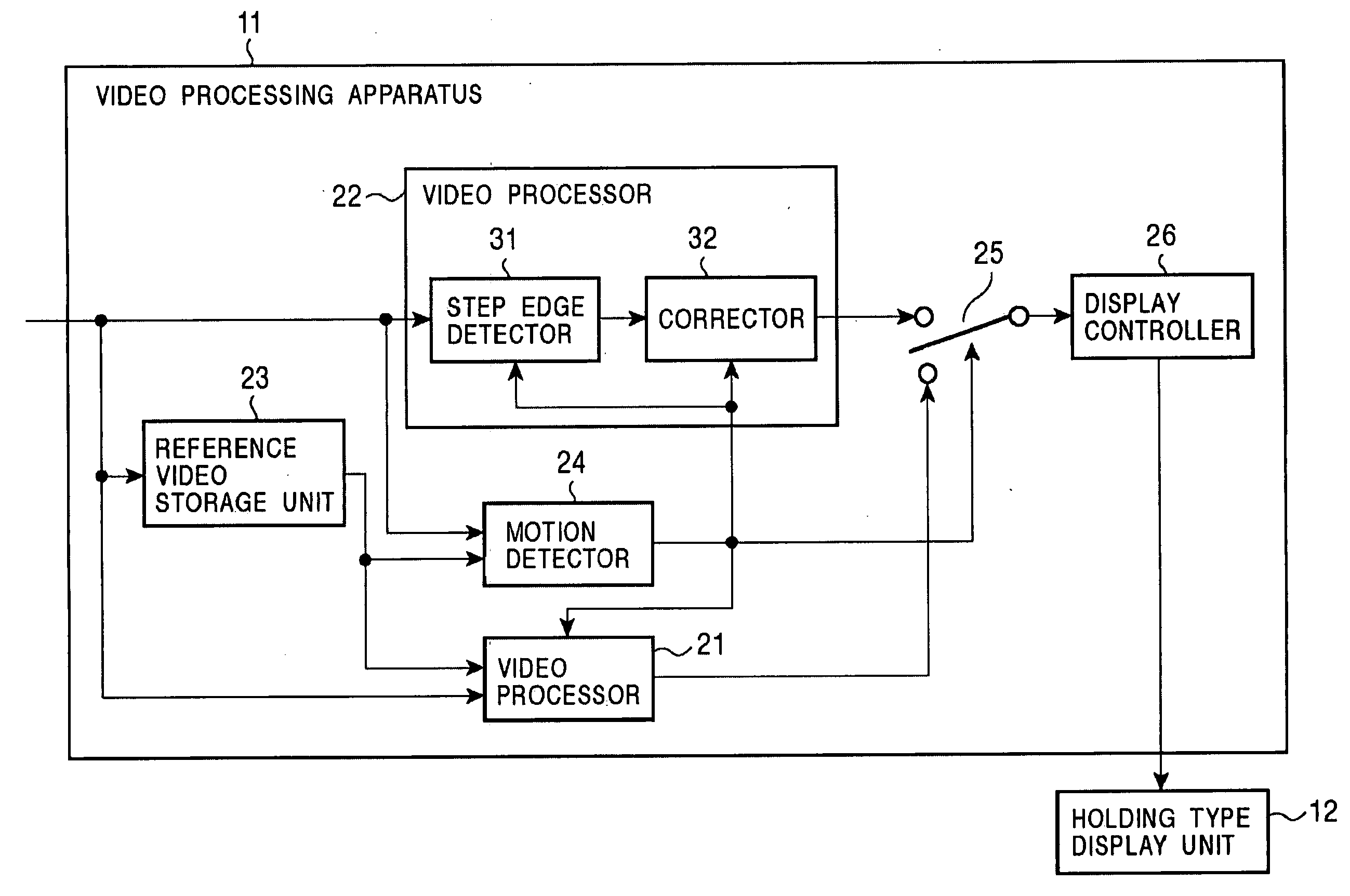
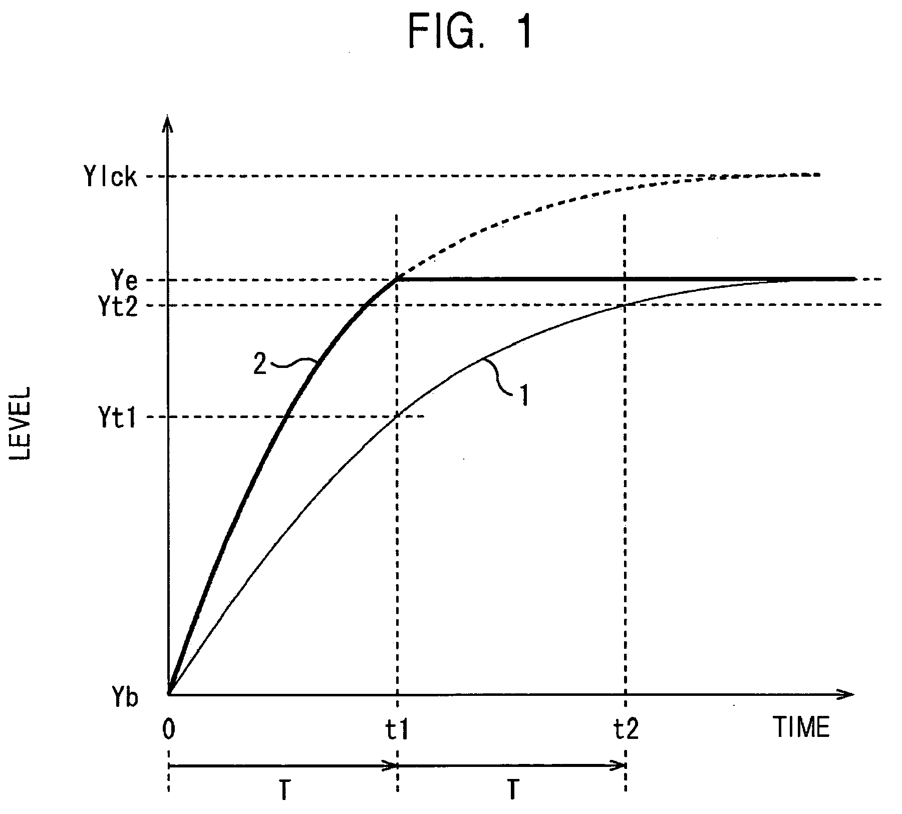
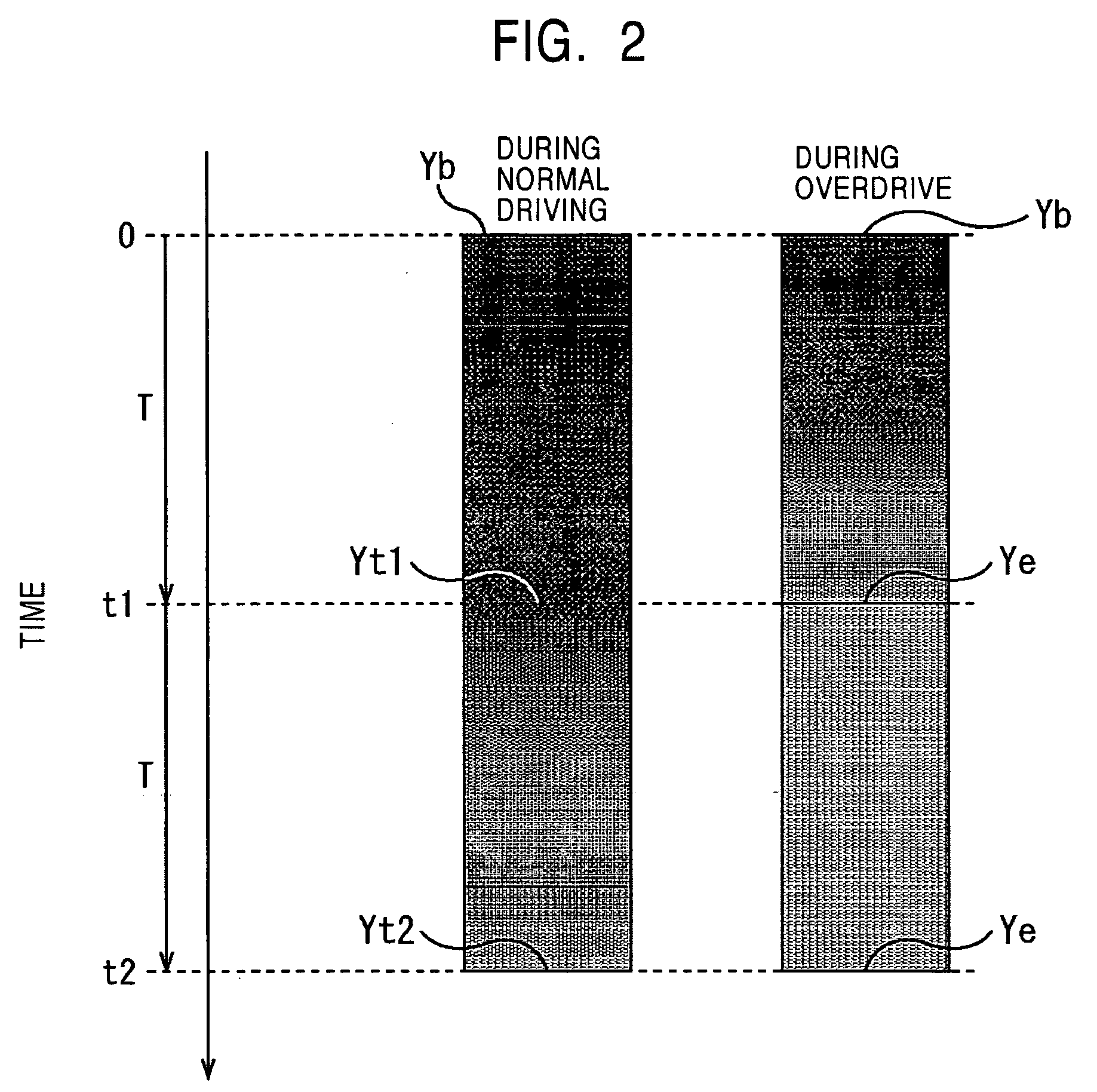
According to the present invention, a first video processing apparatus is provided. This first video processing apparatus includes a unit (for example, a motion detector 24 of FIG. 7) for detecting motion in a video based on input video data (for example, video data currently input to a video processing apparatus 11 of FIG. 7) and reference video data (for example, video data output from a reference video storage unit 23 of FIG. 7) immediately prior to the input video data, a video processing unit (for example, a video processor 22 of FIG. 7) for processing a pixel value in the video data based on the result of the motion detection of the motion detecting unit, and a display unit (a holding type display unit 12 of FIG. 7) for displaying the result of the process of the pixel value provided by the video processing unit. The video processing unit includes a step edge detector (for example, a step edge detector 31 of FIG. 7) for detecting an edge portion in response to the result of t...


PUM

PropertyMeasurementUnit
field timeaaaaaaaaaa
video processingaaaaaaaaaa
heightaaaaaaaaaa

Abstract

A holding type display such as a liquid-crystal display for controlling motion blur is disclosed. A step edge detector detects an edge portion of a moving step edge in video data in an input frame or an input field. A corrector corrects a pixel value of a pixel at the edge portion of the step edge detected by the step edge detector, based on a spatial amount of motion of the corresponding pixel supplied by a motion detector.

Description

BACKGROUND OF THE INVENTION 1. Field of the Invention The present invention relates to a video processing apparatus, a video processing method, and a computer program and, in particular, to a video processing apparatus, a video processing method, and a computer program for controlling motion blur of a moving picture in a holding type display device such as a liquid-crystal display device. 2. Description of the Related Art Cathode-ray tubes (CRTs) are in widespread use as a display for displaying a moving picture. Liquid-crystal displays working in a display method different from the CRT are also widely used (see Japanese Patent Application No. 2001-118396, for example). When a predetermined one of a plurality of frames or fields forming a moving picture is addressed on a CRT, a built-in electron gun successively scans each of horizontal lines (scanning lines) forming the screen of the CRT. The addressed frame or field is thus displayed on the screen of the CRT. Each of a plura...

Claims


Application Information

Patent Timeline
Patent Type & Authority Applications(United States)
IPC IPC(8): G02F1/133G06T5/00G06T7/20G06T7/60G09G3/20G09G3/36
CPCG06T7/0083G06T7/20G06T2207/10016G09G3/20G09G3/3611G06T2207/20192G09G2320/0261G09G2320/106G09G2340/16G06T5/003G09G2320/0252G06T7/12G09G3/30
Inventor NISHI, TORUUEDA, KAZUHIKOASANO, MITSUYASUYOKOYAMA, KAZUKIINADA, TETSUJI
Owner SONY CORP
Why Eureka
Try Eureka