Branch optical wave-guide

a technology of optical waveguides and beams, applied in the direction of optical waveguide light guides, optical light guides, instruments, etc., can solve the problems of undesirable excessive length of waveguides as a whole, inability to consider entire lengths, and undesirable excessive length of thus configured waveguides

Inactive Publication Date: 2005-02-10
SWCC SHOWA DEVICE TECHNOLOGY CO LTD +1
View PDF1 Cites 128 Cited by
  • Summary
  • Abstract
  • Description
  • Claims
  • Application Information

AI Technical Summary

Benefits of technology

[0013] To solve the conventional problems as mentioned above, the present invention provides a branch optical wave-guide that can make its entire length short with polarization property favorably equalized.

Problems solved by technology

According to the Y-branch optical wave-guide path disclosed in Japan Patent Laid-Open Publication No. 5-11130, the length of the wave-guide becomes undesirably too long as a whole.
So, there is a problem that, when using a branch optical wave-guide having a plurality of Y-branch optical wave-guides mutually combined, the resulting entire length cannot be disregarded.
However, similarly, the length of thus configured wave-guide becomes undesirably too long as a whole.
However, under this configuration, there is a problem that unequivalent polarization property is observed in respective output side wave-guides.

Method used


Image

  • Branch optical wave-guide
  • Branch optical wave-guide
  • Branch optical wave-guide

Examples


first embodiment

[0031] [First Embodiment]

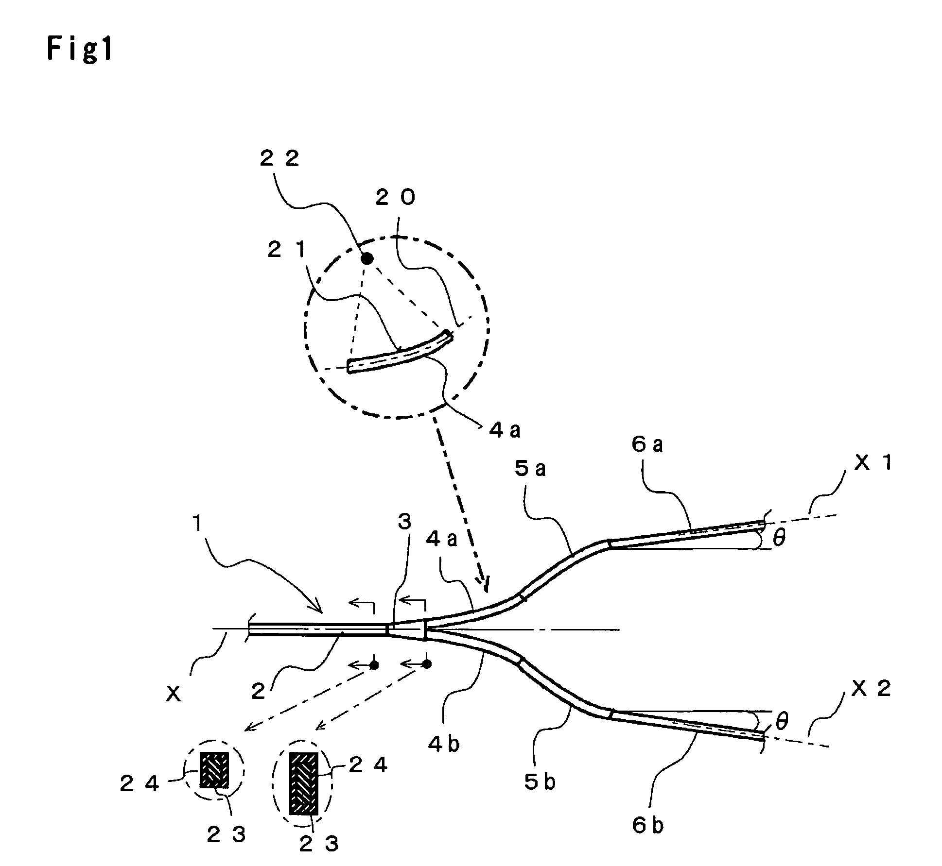
[0032]FIG. 1 shows an embodiment of the branch optical wave-guide according to the present invention.

[0033] As shown in FIG. 1, a branch optical wave-guide 1 of the embodiment has a first linear wave-guide 2 for receiving light, and a tapered branch path 3 that is coupled to the first linear wave-guide 2 and splits light. There is shown an enlarged cross-sectional view of the first linear wave-guide 2 in a left side chain-line circle at the lower left of FIG. 1. The first linear wave-guide 2 has a core 23 and a clad 24. Light is transmitted through the core 23. There is shown an enlarged cross-sectional view of the right end of the tapered branch path 3 in a right side chain-line circle at the lower left of FIG. 1. The tapered branch path 3 is tapered to enlarge the cross-section area of the core 23, so as to split light transmitted through the first linear wave-guide 2. In this embodiment, light is received at the left end of the first linear wave-guide 2 ...

second embodiment

[0039] [Second Embodiment]

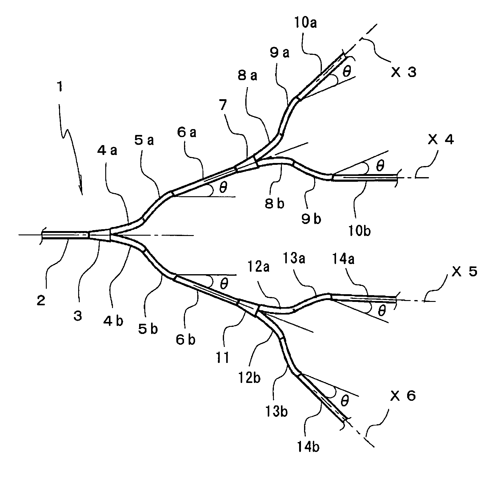
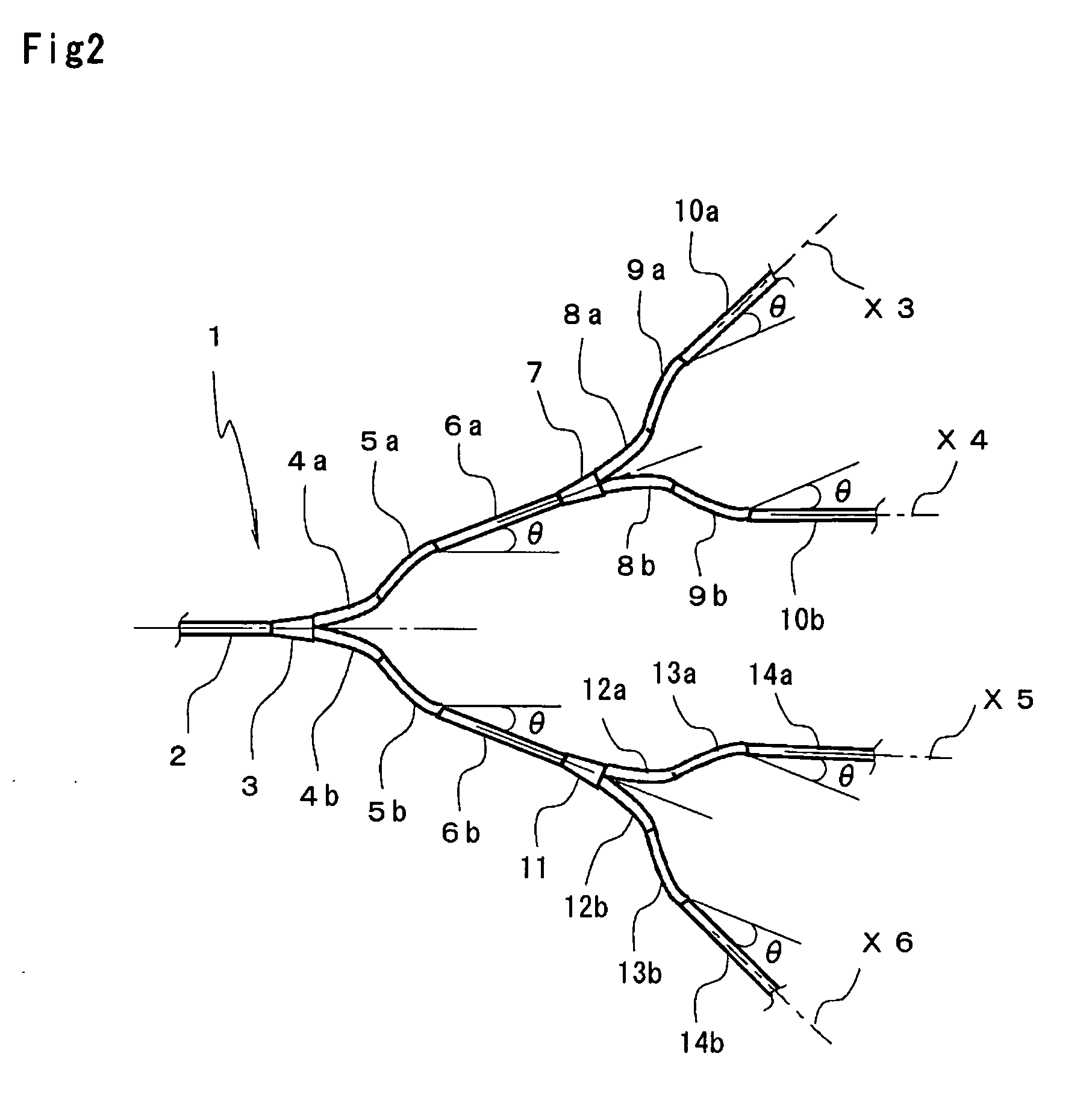
[0040]FIG. 2 shows another embodiment of the branch optical wave-guide according to the present invention. In FIG. 2, parts or components similar to those shown in FIG. 1 are indicated with the same reference numerals.

[0041] The branch optical wave-guide shown in FIG. 2 is of 1×4 type. The second linear wave-guide 6a of the branch optical wave-guide 1 shown in FIG. 1 has its end coupled to a second tapered branch path 7. The second tapered branch path 7 has its end coupled to third curved wave-guides 8a, 8b, and then fourth curved wave-guides 9a, 9b in this order, respectively. Furthermore, the fourth curved wave-guides 9a, 9b have their ends coupled to third linear wave-guides 10a, 10b, respectively. On the other hand, the second linear wave-guide 6b has its end coupled to a second tapered branch path 11. The second tapered branch path 11 has its end coupled to third curved wave-guides 12a, 12b, and then fourth curved wave-guides 13a, 13b in this order, r...

third embodiment

[0043] [Third Embodiment]

[0044]FIG. 3 shows an explanatory diagram for explaining the method of combining the branch optical wave-guides.

[0045] In FIG. 3, branch optical wave-guide paths 1a, 1b, 1c are of the same configuration as the branch optical wave-guide 1 as described above with reference to FIG. 1. For example, when the second linear wave-guide 6b directly coupled to the second curved wave-guide 5b of the branch optical wave-guide 1a is put together and coupled to the first linear wave-guide 2 directly coupled to the tapered branch path 3 of the branch optical wave-guide 1b, a triple branch optical wave-guide is formed. Furthermore, the first linear waveguide 2 of the branch optical wave-guide 1c may be coupled to the second linear wave-guide 6a of the branch optical wave-guide 1b. To reduce the size of thus completed branch optical wave-guide, when coupling the branch optical wave-guide 1a and the branch optical wave-guide 1b, it is desired that the second linear wave-guid...


PUM


Abstract

When the longitudinal central axis line of a first linear wave-guide 2 that receives light is set to be a reference line, open portions of circular arcs of first curved wave-guides 4a, 4b that are coupled to a tapered wave-guide 3 face outward when viewed from the reference line. On the other hand, open portions of circular arcs of second curved wave-guides 5a, 5b that are coupled to the first curved wave-guides 4a, 4b face inward when viewed from the reference line. Furthermore, second linear wave-guides 6a, 6b, which are coupled to the first linear wave-guide through the first and second curved wave-guides, and the reference line X are outwardly coupled to form an angle, which is set to be greater than 0 degree. According to the present invention, there can be provided a branch optical wave-guide that can make its entire length short with polarization property of respective output ports equalized.

Description

[0001] This application claims priority to Japanese Patent Application No. 2003-286701, filed Aug. 5, 2003, the complete disclosure of which is incorporated herein by reference. BACKGROUND OF THE INVENTION [0002] 1. Field of the Invention [0003] The present invention relates to a branch optical wave-guide whose entire length is short and whose polarization dependence is low. [0004] 2. Description of Related Art [0005] Recently, as the Internet is coming into wide use, the need of improving the communication networks is significantly increasing. Optical wave-guides are used in optical fiber networks of main lines or network users to construct the optical communication networks. [0006] In an optical communication network, branch optical wave-guides are used to split an optical signal and direct thus split optical signals to plural circuits, or to composite optical signals incident from plural circuits and direct thus composite optical signal to an optical wave-guide. For example, a Y-...

Claims


Application Information

Patent Timeline
Patent Type & Authority Applications(United States)
IPC IPC(8): G02B6/122G02B6/12G02B6/125G02B6/28
CPCG02B6/2804G02B6/125G02B6/12
Inventor SUMIMOTO, TSUTOMU
Owner SWCC SHOWA DEVICE TECHNOLOGY CO LTD
Why Eureka
Try Eureka