Method and apparatus for controlling high-voltage output in image forming system

Active Publication Date: 2005-02-10
HEWLETT PACKARD DEV CO LP
View PDF10 Cites 2 Cited by
  • Summary
  • Abstract
  • Description
  • Claims
  • Application Information

AI Technical Summary

Benefits of technology

[0009] Accordingly, it is an aspect of the present invention to provide a method and an apparatus to control a high voltage output, while reducing load

Problems solved by technology

Thus, the single-pass method has disadvantages such as high fabrication cost and high sensitivity to e

Method used


Image

  • Method and apparatus for controlling high-voltage output in image forming system
  • Method and apparatus for controlling high-voltage output in image forming system
  • Method and apparatus for controlling high-voltage output in image forming system

Examples


Embodiment Construction

[0022] Reference will now be made in detail to the embodiments of the present invention, examples of which are illustrated in the accompanying drawings, wherein like reference numerals refer to the like elements throughout. The embodiments are described below to explain the present invention by referring to the figures.

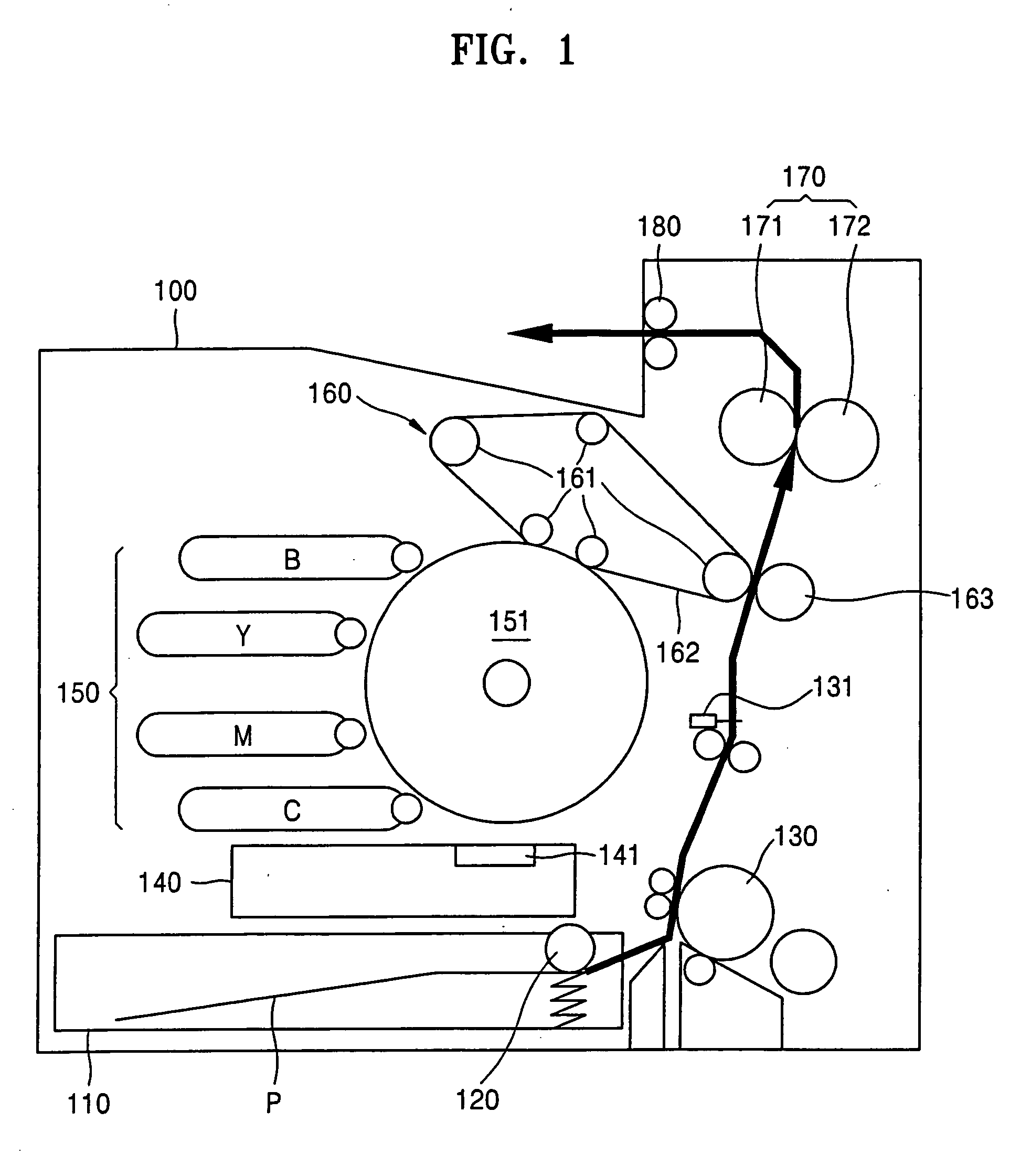
[0023]FIG. 1 is a side cross-sectional view of an image forming system using a method of controlling a high voltage output of the present invention. The image forming system includes a loading device 110, a pickup device 120, a paper feeding device 130, an exposure device 140, a developing device 150, a transfer device 160, a fusing device 170, and a paper discharging device 180.

[0024] Referring to FIG. 1, the loading device 110, which generally includes a cassette to carry sheets of paper therein, is removably installed in a lower portion of a main body 100. The paper P is picked up by the pickup device 120, which is rotatably installed to rotate in the main body 1...


PUM


Abstract

A method and an apparatus to control a high voltage output in an image forming system. The method includes setting a master processor to control an engine, and setting a slave processor to control a high voltage output; transmitting a command, which includes a timing and a level of the high voltage output, from the master processor to the slave processor; and determining the timing and level of the high voltage output after analyzing the received command, and controlling the high voltage output according to a predetermined high voltage output synchronization signal by the slave processor.

Description

CROSS-REFERENCE TO RELATED APPLICATIONS [0001] This application claims the priority of Korean Patent Application No. 2003-53907, filed on Aug. 4, 2003, in the Korean Intellectual Property Office, the disclosure of which is incorporated herein in its entirety by reference. BACKGROUND OF THE INVENTION [0002] 1. Field of the Invention [0003] The present invention relates to an image forming system, and more particularly, to a method and an apparatus to control a high voltage output while reducing loads on a main processor in an engine controlling module by simplifying a control signal line. [0004] 2. Description of the Related Art [0005] In an image forming system using an electro-photographic method, when light corresponding to image information is scanned by an exposure device onto a photosensitive medium which is thus charged to a predetermined electric potential, an electrostatic latent image is formed on the photosensitive medium. Then, a developer provides toner on the electrosta...

Claims


Application Information

Patent Timeline
IPC IPC(8): G03G15/00G03G21/00B41J29/38G03G21/14G06F3/12
CPCG03G2215/00025G03G15/5004G06F3/12
Inventor EOM, YOON-SEOP
Owner HEWLETT PACKARD DEV CO LP
Why Eureka
Try Eureka