
Channel selection method, and wireless station and wireless terminal employing it

a wireless network and channel selection technology, applied in the field of communication channel selection method and wireless station and wireless terminal employing it, can solve the problems of communication disconnection time, degraded communication performance of its own system, and inability to connect to the ap and the terminal, so as to achieve the effect of drastically reducing the load of each ap

Active Publication Date: 2005-02-10
NEC CORP
View PDF14 Cites 27 Cited by
  • Summary
  • Abstract
  • Description
  • Claims
  • Application Information

AI Technical Summary

Benefits of technology

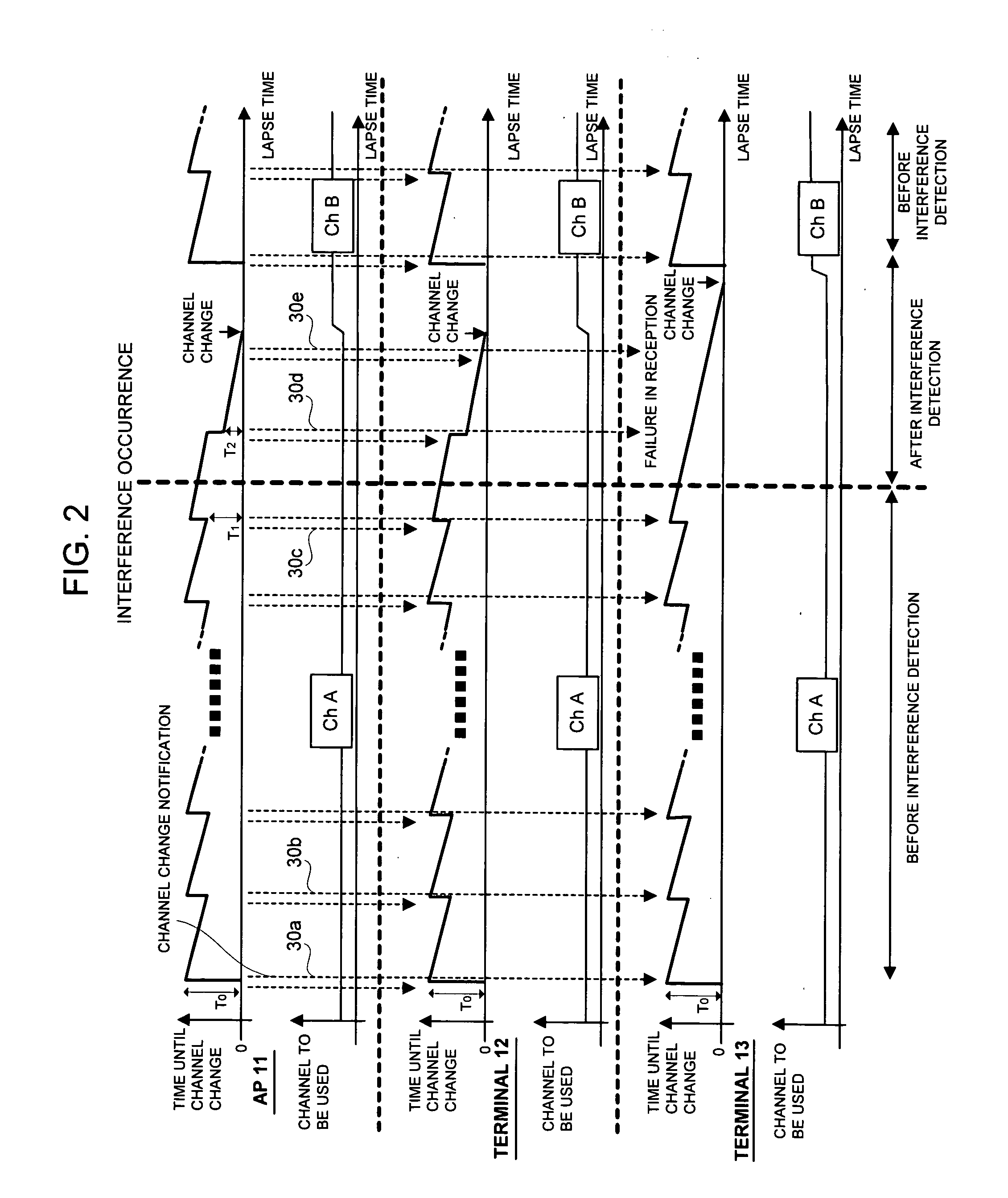
[0018] An advantageous operation of the present invention will be described. In a channel selection method in a communication system for making communication between a first wireless station and one or each of a plurality of second wireless stations different from this first wireless station by employing one of a plurality of wireless channels, the first wireless station transmits a first channel change notification including a first time until a channel change and a change destination channel to the second wireless station, and prior to a lapse of the above first time, transmits a second channel change notification including a second time until a channel change and a change destination channel to the above second wireless station. And, the first and the second wireless stations are adapted to assume the time until the channel change to be the second time. Doing so allows a connection to the AP to be prevented from being disconnected in a case where the terminal failed to receive the channel change notification message from the AP due to occurrence of the interference.
[0019] In accordance with a first to third embodiments of the present invention, the effect exists that the AP transmits the channel change notification message to the terminal prior to occurrence of the interference, thereby allowing the terminal that failed to receive the channel change notification message at the time of the interference occurrence to make a channel change without causing a connection to the AP to be disconnected.
[0020] Also, in accordance with a fourth embodiment of the present invention, the effect exists that the AP transmits the channel change notification message to the terminal plural times only after occurrence of the interference, thereby allowing the provability that the channel change notification message is received in all terminals to be enhanced while a traffic amount before the interference occurrence is curtailed.
[0021] Further, in accordance with a fifth and a sixth embodiments of the present invention, the effect exists that the AP itself checks each interference status of a plurality of the channels, and decides to assume the optimum channel to be a change destination channel, whereby the effect exists that a change to the optimum channel is made possible after the interference occurrence.
[0022] Further, also, in accordance with a seventh embodiment of the present invention, the effect exists that a management server that manages the AP manages the channel that each AP uses, and the interference status of each channel collectively, decides the change destination channel based upon these, and notifies it to each AP, thereby allowing a load of each AP to be alleviated drastically. Also, the server can make a supervisory management of the situation of each AP and the interference status of each channel, which makes it possible to take a control in such a manner that the interference occurrence is suppressed as a whole of the area.

Problems solved by technology

At this moment, interference between the neighboring wireless LAN systems that causes communication performance of its own system to degrade due to a radio wave to be transmitted by the other system.
Accordingly, when the AP made a channel change, the terminal is not able to recognize it, which causes a connection between the AP and the terminal to be disconnected.
That is, the conventional wireless LAN system based upon the IEEE 802.11 standard had the problem that a communication disconnection time during which communication between the wireless stations became impossible to make because of the use channel change by the wireless LAN system became long.
A transmission error exists intrinsically in the wireless communication, so the possibility exists that the terminal is not able to receive the channel change notification message from the AP correctly.
That is, there is the problem that the terminal, which is not able to make a channel change at a timing that the AP intended due to the transmission error, can exist.

Method used


Image

  • Channel selection method, and wireless station and wireless terminal employing it
  • Channel selection method, and wireless station and wireless terminal employing it
  • Channel selection method, and wireless station and wireless terminal employing it

Examples


embodiment 1

[0049] [Embodiment 1]

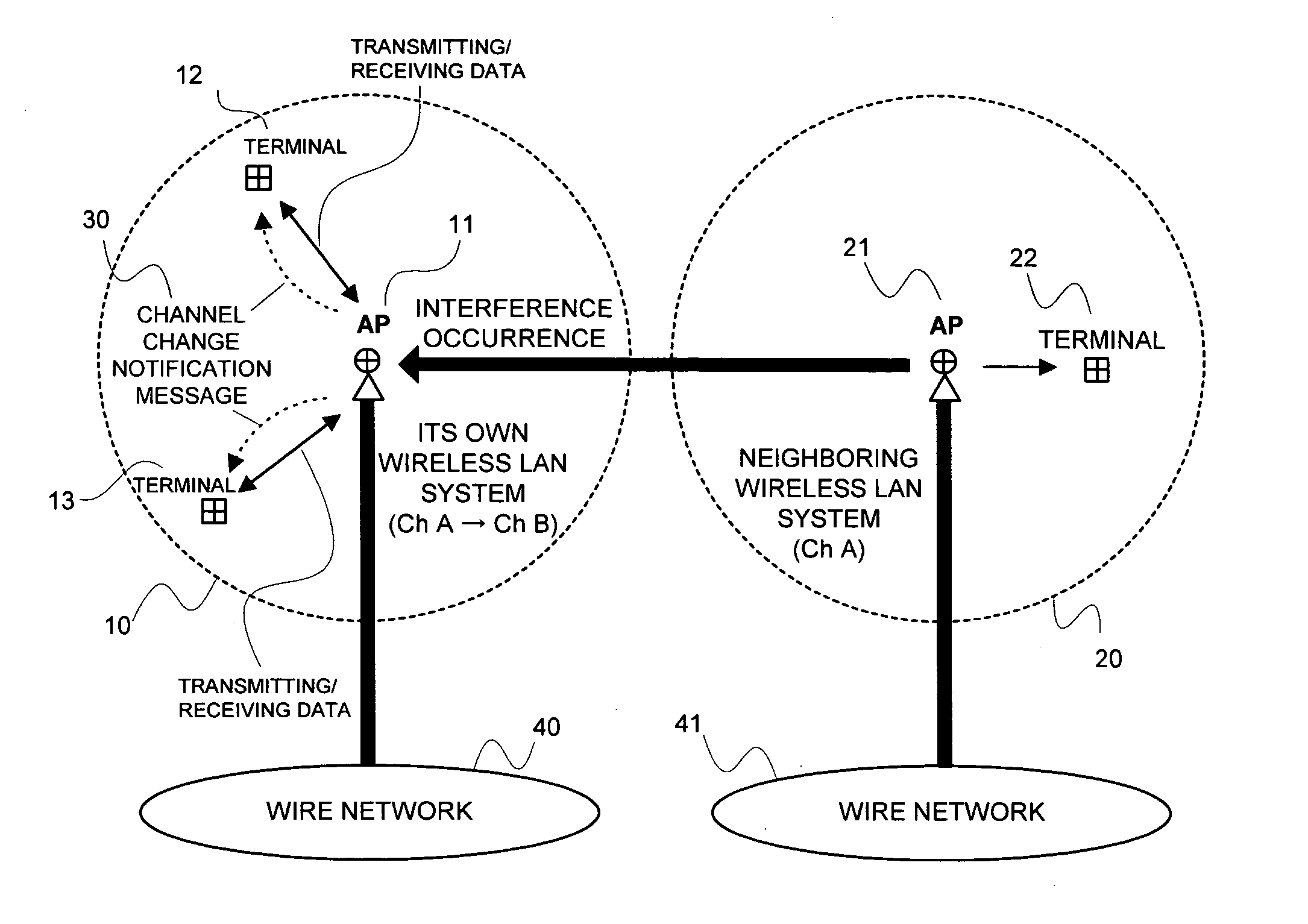
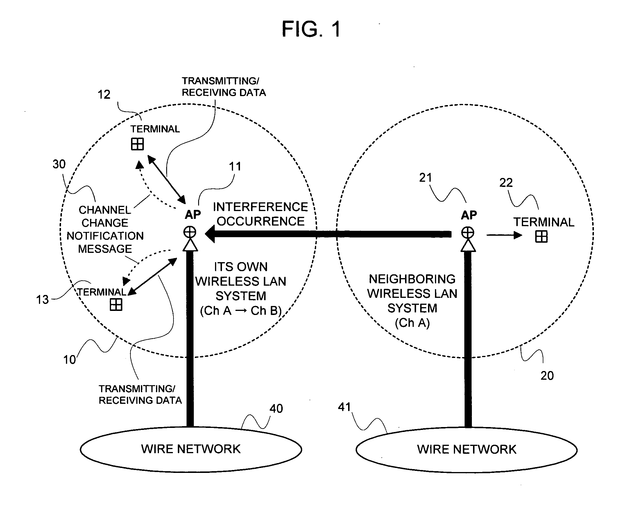
[0050] Next, the embodiments of the present invention will be explained in details, by making a reference to the accompanied drawings. FIG. 1 illustrates a network system in the first embodiment of the present invention. A wireless LAN system 10 that is configured of an access point (hereinafter, expressed as an AP) 11 and wireless terminals 12 and 13, and a wireless LAN system 20 that is configured of an AP 21 and a wireless terminal 22 exist herein. Also, the AP 11 is connected to a wire network 40, which allows the wireless terminals 12 and 13 to make communication with appliances on the wire network 40 via the AP 11. Similarly, the AP 21 is connected to a wire network 41, which allows the wireless terminal 22 to make communication with the appliances on the wire network 41.

[0051] Additionally, in FIG. 1, the wire network 40 and the wire network 41 were separated for illustration; however a single wire network may be configured of these.

[0052] In this embod...

embodiment 2

[0103] [Embodiment 2]

[0104] As the case may be, the interference status is improved during the time until the channel change is executed since the interference detection in the foregoing first embodiment. A necessity for the channel change is lost in such a case, so a technique adapted to continuously use a channel identical to the channel before the interference detection is a second embodiment.

[0105]FIG. 8 is a timing chart illustrating an operation of the second embodiment of this FIG. 2, and parts identical to that of FIG. 2 are indicated with identical codes. By making a reference to FIG. 8, after the interference detection, the AP 11 transmits the channel change notification message 30d to the terminals 12 and 13; however when the interference status is improved within the channel change time by this message 30d, the interference detection means 105 (see FIG. 3) detect this, and make an operation so that the time until the channel change, which is a time longer than the curre...

embodiment 3

[0109] [Embodiment 3]

[0110] Next, a third embodiment of the present invention will be explained. In this embodiment, the channel change notification message is transmitted before the interference occurrence, and the transmission of the channel change notification message is not made after the interference occurrence. Making a channel change notification in advance before the interference occurrence aims at enhancing the provability that the channel change notification message is received in the wireless terminal.

[0111]FIG. 11 is a timing chart illustrating an operation of this embodiment, and parts identical to that of FIG. 2 are indicated with identical codes. FIG. 12 is a flowchart illustrating an operational procedure of the AP 11 of this case, and steps identical to that of FIG. 5 are indicated with identical codes. By making a reference to these FIG. 12 and FIG. 13, in this embodiment, the AP 11 has an operation identical to that of the first embodiment shown in FIG. 2 and FIG...


PUM


Abstract

At the time of a normal operation, a second channel change message 30b is transmitted from the AP to each terminal before a time T0 until a channel change that is included in a first channel change message 30a elapses, thereby all terminals that received this message 30b, and the AP stop changing the channel. At the time of interference occurrence, setting a time until a channel change to be filed in a third channel change message 30d to a time equal to or less than a lapse time until the channel change at the time point of transmitting this message 30d to transmit it to each terminal from the AP allows the terminal that failed to receive the message at the time of the interference occurrence to make a channel change without causing a connection to the AP to be disconnected.

Description

BACKGROUND OF THE INVENTION [0001] The present invention relates to a communication channel selection method, and a wireless station and a wireless terminal employing it, and more particularly to an interference avoidance technique in a wireless network system. [0002] A wireless LAN system to be represented by the 802.11 standard standardized in the Institute of Electrical and Electronics Engineers (hereinafter, described as the IEEE), which is generally configured of an access point (AP) for connecting a wireless network and a wire network, and a plurality of wireless terminals, in which mutual communication is made by employing one of a plurality of frequency channels that are available. In such a wireless LAN system, however, a shared frequency band requiring no license is generally utilized, whereby the possibility exists that neighboring other wireless LAN systems utilize an identical frequency channel. At this moment, interference between the neighboring wireless LAN systems t...

Claims


Application Information

Patent Timeline
Patent Type & Authority Applications(United States)
IPC IPC(8): H04W36/06H04L12/28
CPCH04W36/06
Inventor MIYASHITA, AKIRA
Owner NEC CORP
Learn More