Exercise apparatus using weight and pneumatic resistances

a technology of pneumatic resistance and exercise equipment, applied in the field of adjustable exercise equipment, can solve the problems of not providing the feel to which people are accustomed, and achieve the effect of reducing the impact on joints

Active Publication Date: 2005-02-10
KEISER
View PDF32 Cites 48 Cited by
  • Summary
  • Abstract
  • Description
  • Claims
  • Application Information

AI Technical Summary

Benefits of technology

[0008] An aspect of the present invention involves the recognition of a need for an exercise machine that combines the advantages of free weights (e.g., balance control training, freedom of movement) with the advantages of pneumatic resistance (e.g., applied resistance throughout exercise stroke, reduced impact on joints, use for developing explosive power). In accordance with this aspect of the present invention, an exercise apparatus comprises a user interface adapted to be moved by a user towards and away from a stationary portion of the user's body (e.g., a center of the user's torso when bench pressing or the user's feet when squatting). A weight is selectively coupled to the user interface, and a pneumatic resistance device is also selectively coupled to the user interface independently of the weight. The pneumatic resistance device includes at least one valve to regulate the amount of resistance that the pneumatic resistance device applies to oppose movement of the user interface in at least one direction away from or towards the stationary portion of the user's body.

Problems solved by technology

Accordingly, for many weight lifters, pneumatic exercise equipment does not provide the feel to which they are accustomed.

Method used


Image

  • Exercise apparatus using weight and pneumatic resistances
  • Exercise apparatus using weight and pneumatic resistances
  • Exercise apparatus using weight and pneumatic resistances

Examples


Embodiment Construction

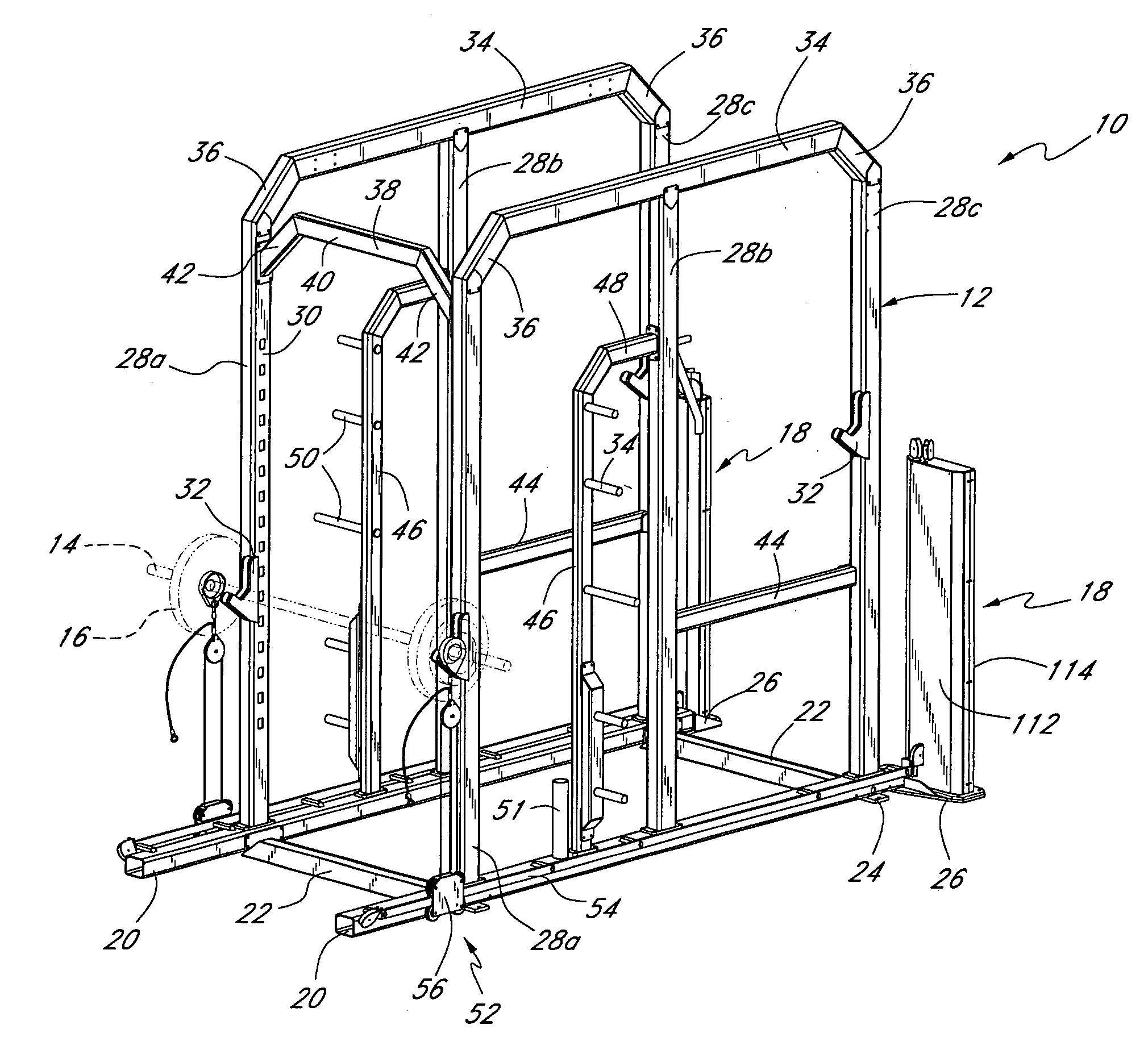
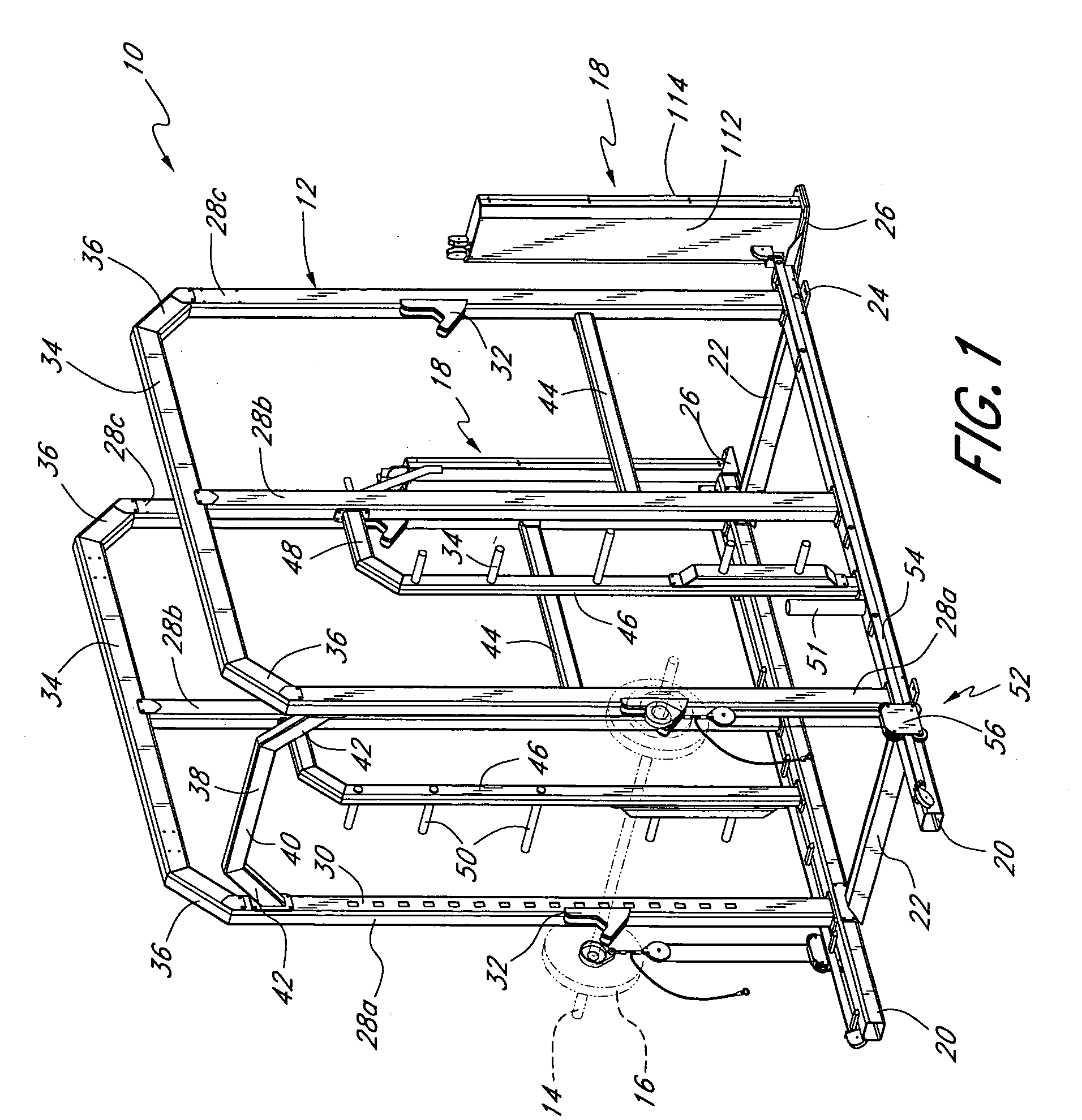
[0031] The exercise apparatus 10 illustrated in FIG. 1 marries traditional weight training with pneumatic-resistance training. While the present embodiment illustrates the apparatus as adapted for use with free-weights, the apparatus can also be used with one or more weight stacks or other weight-based resistance devices. Alternatively, the exercise apparatus 10 can be used solely with pneumatic resistance but may facilitate movements similar to those used with free weights.

[0032] The exercise apparatus 10 includes a frame 12 that can support a weight-lifting bar 14 (“weight bar”) and a plurality of free weight plates 16. The frame 12 defines at least one exercise station (either a half or a full station) and preferably two or more stations. The embodiment illustrated in FIG. 1 includes one full station and one half station. A user can sit, stand or recline at each station. For example, a bench can be used in a well known manner with the illustrated exercise apparatus 10, as shown ...


PUM


Abstract

An exercise apparatus combines weight and pneumatic resistance to provide a user with options to work against either or both types of resistances. In one mode, the exercise apparatus includes a user interface, such as, for example, a weight-lifting bar, that a user can move either toward or away from a stationary portion of the user's body. A weight (e.g., a free weight plate) can be selectively coupled to the user interface. A pneumatic resistance device can also be selectively coupled to the user interface independent of whether the user interface is also coupled to the weight. The pneumatic resistance device includes at least one valve to regulate the amount of resistance that the pneumatic resistance device applies to oppose movement of the user interface in at least one direction. At least one actuator may be provided for controlling the at least one valve, the actuator being configured to be manipulated by the user while the user is in an exercise position. The apparatus can also include a trolley that moves relative to a track. The trolley can move with the user interface so as to permit various positions of the user interface relative to the pneumatic resistance device.

Description

RELATED APPLICATIONS [0001] This application claims priority under 35 U.S.C. §119(e) to U.S. Provisional Application No. 60 / 483,573, filed on Jun. 27, 2003, U.S. Provisional Application No. 60 / 555,577, filed on Mar. 22, 2004, and U.S. Provisional Application No. 60 / 555,723, filed on Mar. 23, 2004, the entire contents of which are herein incorporated by reference in their entirety.BACKGROUND OF THE INVENTION [0002] 1. Field of the Invention [0003] The present invention relates to an exercise apparatus and, more particularly, to an adjustable exercise apparatus that allows for variable amounts of resistances to be applied using weight resistance (e.g., iron plates), pneumatic resistance, or both weight and pneumatic resistances. [0004] 2. Description of the Related Art [0005] Weight lifting for exercise and strength training commonly involves lifting iron weights. Typically, the weights are fixed to a bar (e.g., a barbell), are freely added to or removed from a weight-lifting bar (e.g...

Claims


Application Information

Patent Timeline
Patent Type & Authority Applications(United States)
IPC IPC(8): A63B21/008A63B21/06A63B21/072A63B21/078
CPCA63B21/00058A63B21/0087A63B21/0724A63B21/075A63B21/00069A63B2225/30A63B21/00065A63B21/00072A63B21/078
Inventor KEISER, DENNIS L.
Owner KEISER
Why Eureka
Try Eureka