Object observation system and method of controlling object observation system

a technology of object observation and observation system, which is applied in the field of object observation system and a method of controlling an object, can solve the problem of difficult to accurately bring the distal end of an endoscope to a target part in a short period of tim

Inactive Publication Date: 2005-02-10
OLYMPUS CORP
View PDF13 Cites 141 Cited by
  • Summary
  • Abstract
  • Description
  • Claims
  • Application Information

AI Technical Summary

Problems solved by technology

In a tract inside of the body having multi-level branches such as the bronchi, when a position of an abnormal part is close to t

Method used


Image

  • Object observation system and method of controlling object observation system
  • Object observation system and method of controlling object observation system
  • Object observation system and method of controlling object observation system

Examples


first embodiment

[0147] [First Embodiment]

[0148] An embodiment of the invention will be described below with reference to drawings.

[0149] [First Embodiment]

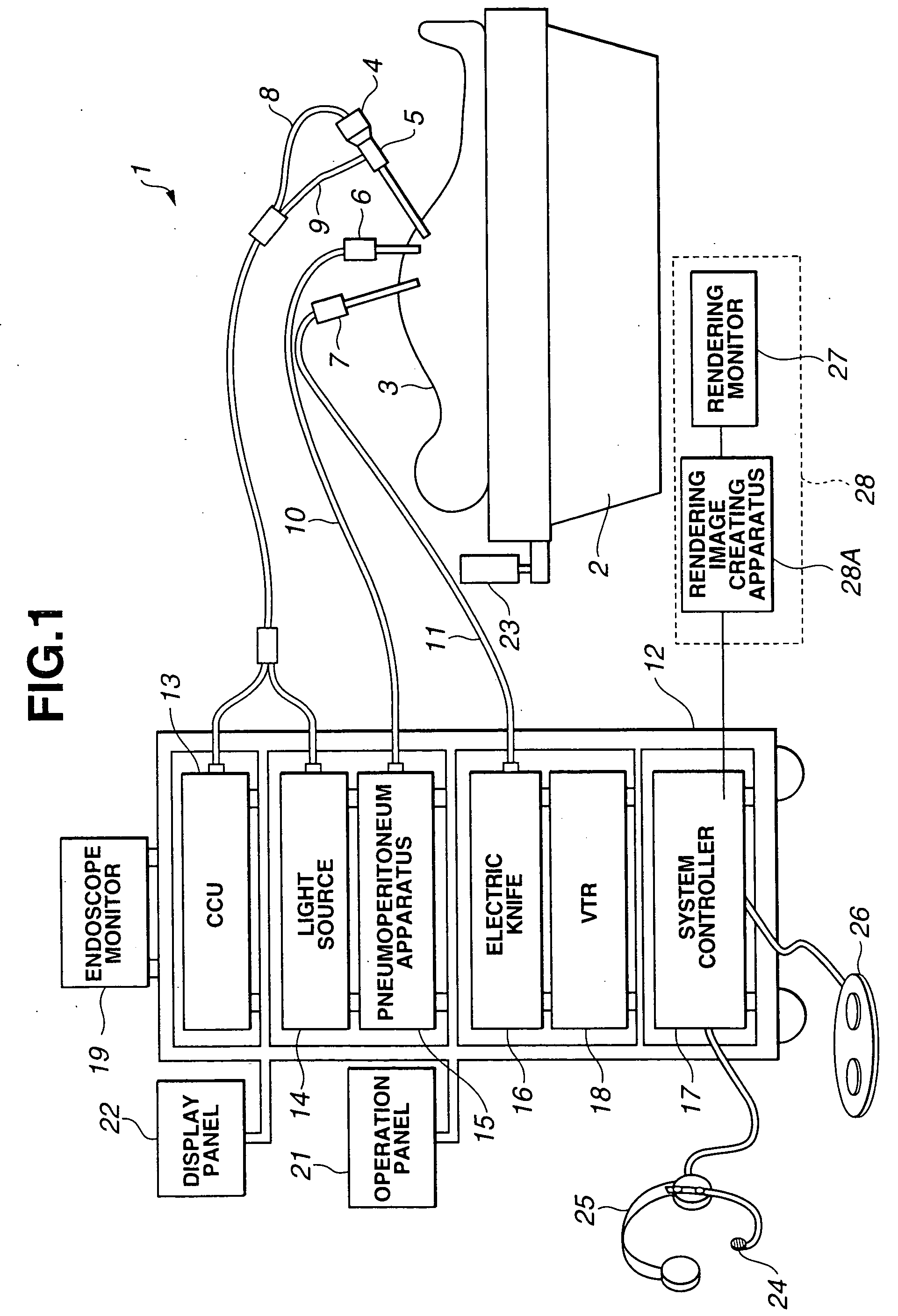
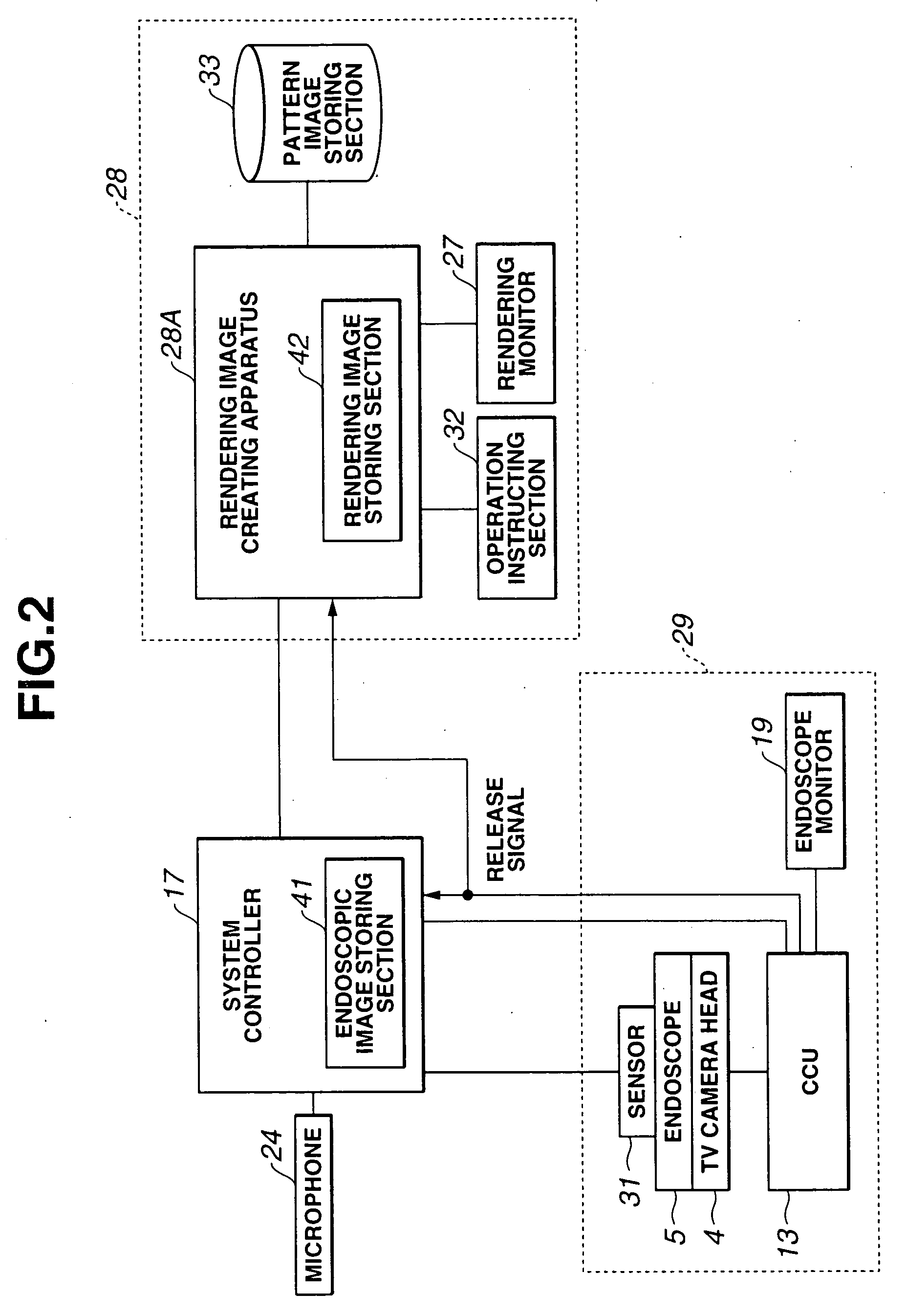
[0150] FIGS. 1 to 3 relate to a first embodiment of the invention. FIG. 1 is an entire configuration diagram showing an endoscopic surgery system according to the first embodiment. FIG. 2 is a circuit block diagram of an endoscope apparatus and rendering apparatus in FIG. 1. FIG. 3 is a control flowchart of a system controller in FIG. 1.

[0151] As shown in FIG. 1, an endoscopic surgery system 1 according to the first embodiment is an object observation system. The endoscopic surgery system 1 has a rigid endoscope (often simply called endoscope, hereinafter), which is inserted to an abdominal cavity of a patient 3, which is a body to be examined, lying on an operation table 2 through a trocar (not shown). A TV camera head 4 self-containing an image pickup apparatus is attached to the rigid endoscope 5. The endoscopic surgery system 1 includes a p...

second embodiment

[0183] [Second Embodiment]

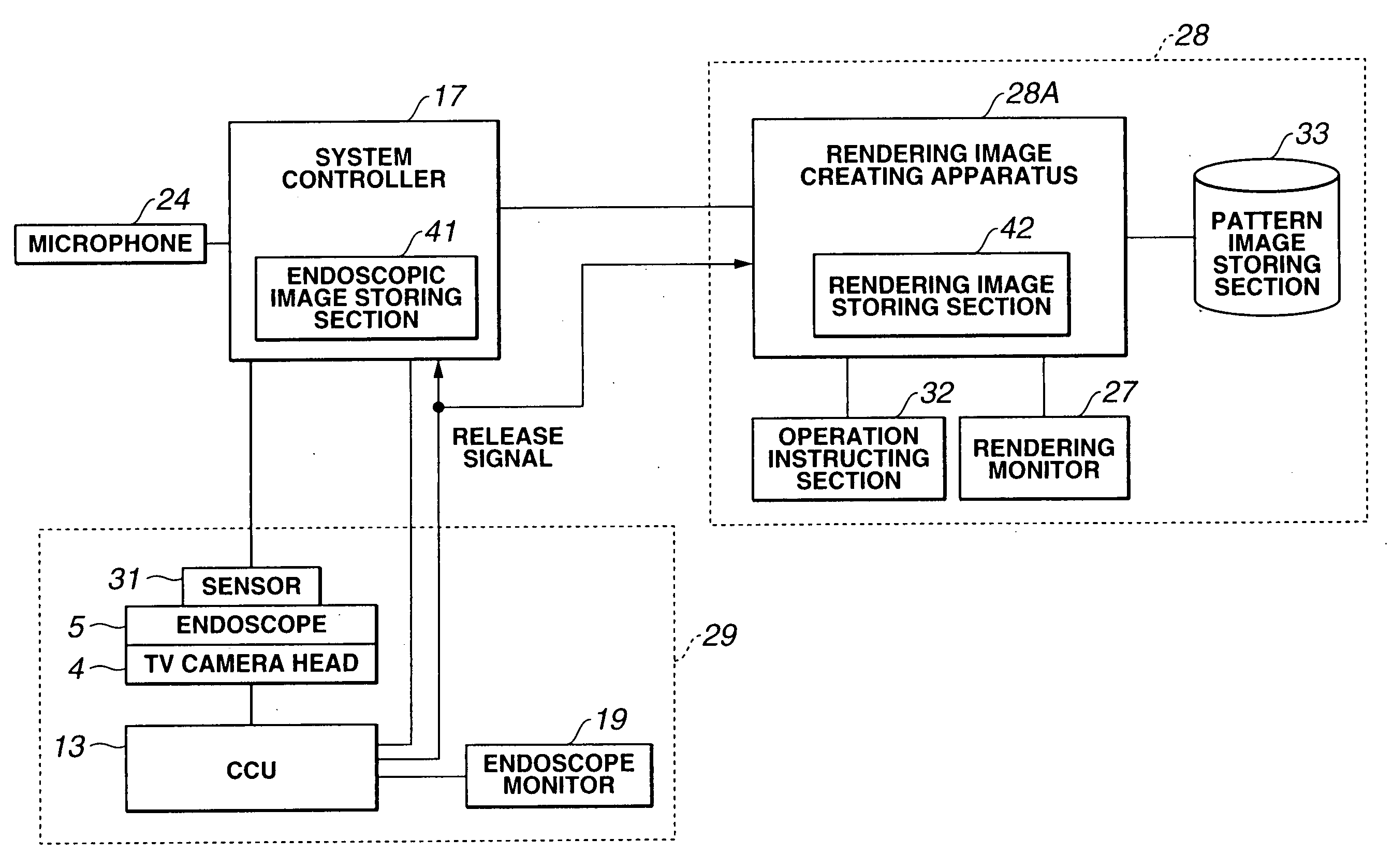
[0184] FIGS. 4 to 8 relate to a second embodiment of the invention. FIG. 4 is a circuit block diagram of an endoscope apparatus and rendering apparatus included in an endoscopic surgery system according to the second embodiment. FIG. 5 is a control flowchart of a system controller in FIG. 4. FIG. 6 is a circuit block diagram of an endoscope apparatus and rendering apparatus showing a variation example of FIG. 4. FIG. 7 is a control flowchart of a system controller showing a variation example of FIG. 5. FIG. 8 is a display example of a synthesized image.

[0185] While, according to the first embodiment, rendering image data and the still image data of an endoscopic image are associated and are recorded in separate storing portions, rendering image data and the still image data of an endoscopic image are recorded in a same storing portion according to the second embodiment. Since the other construction is the same as the one according to the first embodiment, ...

third embodiment

[0210] [Third Embodiment]

[0211] FIGS. 9 to 15 relate to the third embodiment of the invention. FIG. 9 is an entire configuration diagram showing an endoscopic surgery system. FIG. 10 is a circuit block diagram of an endoscope apparatus and rendering apparatus in FIG. 9. FIG. 11 is a flowchart of image processing to be performed by a rendering image creating apparatus in FIG. 9. FIG. 12 is an image display example showing a rendering image of the inside of a body cavity around a target part, which is created by the rendering image creating apparatus in FIG. 9. FIG. 13 is a conceptual diagram showing processing pattern images extracted from a rendering image of the inside of the body cavity in FIG. 12 and a synthesized image created by synthesizing these processing pattern images. FIG. 14 is an image display example of the synthesized image in FIG. 13 after subtraction processing. FIG. 15 is a conceptual diagram in which a desired rendering image is obtained by directly instructing se...


PUM


Abstract

An object observation system of the present invention has an observation apparatus for observing a body to be examined, a three-dimensional image recording apparatus for recording three-dimensional images, which are obtained in advance, of the body to be examined, and an image constructing apparatus for constructing a three-dimensional image based on images in synchronization with the observation apparatus, which are recorded in the three-dimensional image recording apparatus.

Description

[0001] This application claims benefit of Japanese Application Nos. 2003-157041 filed on Jun. 2, 2003, 2003-157042 filed on Jun. 2, 2003, 2003-189784 filed on Jul. 1, 2003, 2003-189785 filed on Jul. 1, 2003, 2004-024828 filed on Jan. 30, 2004, 2004-024829 filed on Jan. 30, 2004, 2004-024830 filed on Jan. 30, 2004, 2004-024831 filed on Jan. 30, 2004, 2004-024832 filed on Jan. 30, 2004, 2004-024833 filed on Jan. 30, 2004, the contents of which are incorporated by this reference. BACKGROUND OF THE INVENTION [0002] 1. Field of the Invention [0003] The present invention relates to an object observation system and a method of controlling an object observation. system. [0004] 2. Description of Related Art [0005] Endoscope apparatuses have been widely used in medical fields and industrial fields. In the endoscope apparatus, an endoscopic image obtained by a television camera externally installed endoscope in which a television camera is attached to an eyepiece portion of an optical endoscop...

Claims


Application Information

Patent Timeline
IPC IPC(8): A61B1/04A61B1/045A61B5/06A61B5/107A61B17/00A61B17/02A61B19/00G06T7/00
CPCA61B1/00009G06T2207/30004A61B1/00041A61B1/0005A61B1/042A61B1/045A61B5/06A61B5/1076A61B17/0281A61B19/26A61B19/52A61B19/5212A61B19/5225A61B19/5244A61B19/56A61B2017/00199A61B2017/00207A61B2017/00216A61B2019/2269A61B2019/262A61B2019/505A61B2019/5229A61B2019/5231A61B2019/5248A61B2019/5251A61B2019/5291A61B2019/566G06T7/0024G06T15/08G06T19/003A61B1/00039A61B2090/502A61B90/36A61B2090/373A61B2034/2048A61B2034/256A61B34/20A61B34/25A61B90/361A61B90/50A61B34/74A61B2034/105A61B90/37A61B2090/372A61B2034/2051A61B2090/365G06T7/30A61B5/062G16H20/40G16H40/63A61B1/0004A61B1/00194A61B1/000094A61B1/00042
Inventor OZAKI, TAKASHITASHIRO, KOICHIFUJITA, MASAYAGOTANDA, MASAKAZUUCHIKUBO, AKINOBUNAKAMURA, TAKEAKI
Owner OLYMPUS CORP
Why Eureka
Try Eureka