Kink resistant cannula having buckle resistant apertures

a cannula and buckle technology, applied in the field of medical cannulas, can solve the problems of unfavorable buckle phenomenon, damage to the side of the vessel wall in the patient, and more trauma to the surrounding tissu

Active Publication Date: 2005-02-10
MEDTRONIC INC
View PDF61 Cites 122 Cited by
  • Summary
  • Abstract
  • Description
  • Claims
  • Application Information

AI Technical Summary

Benefits of technology

[0014] The invention further relates to a cannula having a body with a proximal end and a distal end and a tip on the distal end for engaging the heart as described above as a venous or arterial cannula. A lumen formed in the body extending from the proximal end to the tip forming a fluid path through the cannula. The cannula has one or more reinforcing ribs formed surrounding the lumen. The ribs prevent kinking to hold the lumen open. The ribs may be tapered or straight and extend from the body inward towards a longitudinal axis of the lumen. The ribs may have a top having a concave, rounded or flat shape. The ribs may be interconnected by a link forming an inner wall around the lumen and a fluid passageway between the ribs. The link may have a concave surface forming a smooth bore around the lumen. The fluid passageways may be pressurized from an outside source to provide support to the sidewall of the tip. The cannula further may be configured as a venous cannula having a plurality of non-circular apertures in the wall.

Problems solved by technology

Another challenge of cannula design is the minimization of buckling of the apertures in the walls of the cannula.
The buckling phenomenon is undesirable because the portion of the aperture that buckles outward creates a scoop that extends outward from the cannula wall and may damage the sides of a vessel wall in the patient.
A buckled aperture interrupts the smooth outer surface of the cannula and may cause more trauma to the surrounding tissue if it is rubbed against a sidewall.
A reinforcing wire is used to prevent kinking of the cannula in some designs but creates dimension limitations.

Method used


Image

  • Kink resistant cannula having buckle resistant apertures
  • Kink resistant cannula having buckle resistant apertures
  • Kink resistant cannula having buckle resistant apertures

Examples


Embodiment Construction

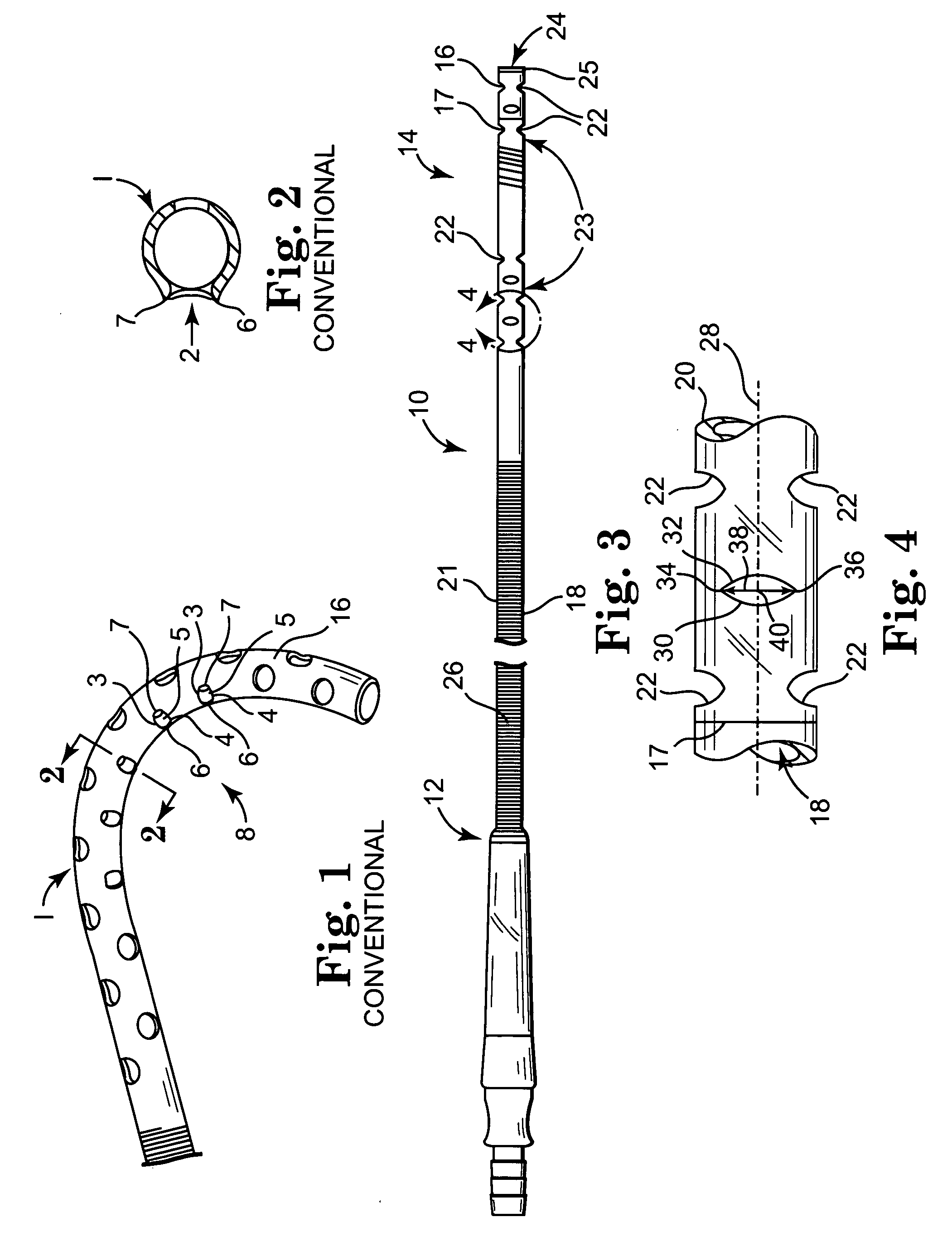
[0040] A conventional catheter or cannula 1 having a flexible tip 16 is shown in FIG. 1. The tip 16 has a plurality of holes 5 that are shown buckling causing an edge to push outward like a scoop, from the profile of the tip at portions 6 and 7. The sides 3, 4 of individual apertures 5 on the concave side 8 are necessarily pushed toward one another as the cannula 1 is bent. As the sides 3, 4 close toward one another, the apertures 5 may buckle outward at other sides 6, 7 as shown in FIG. 2.

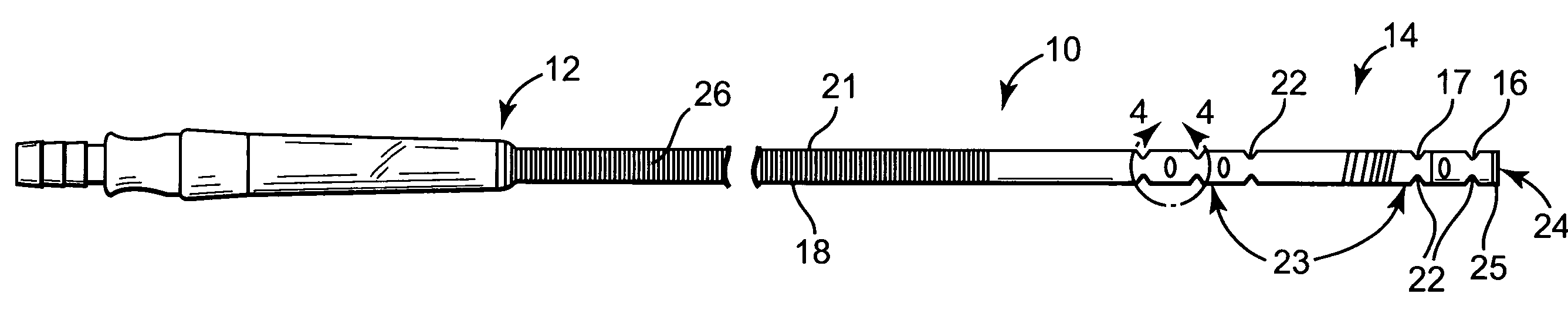
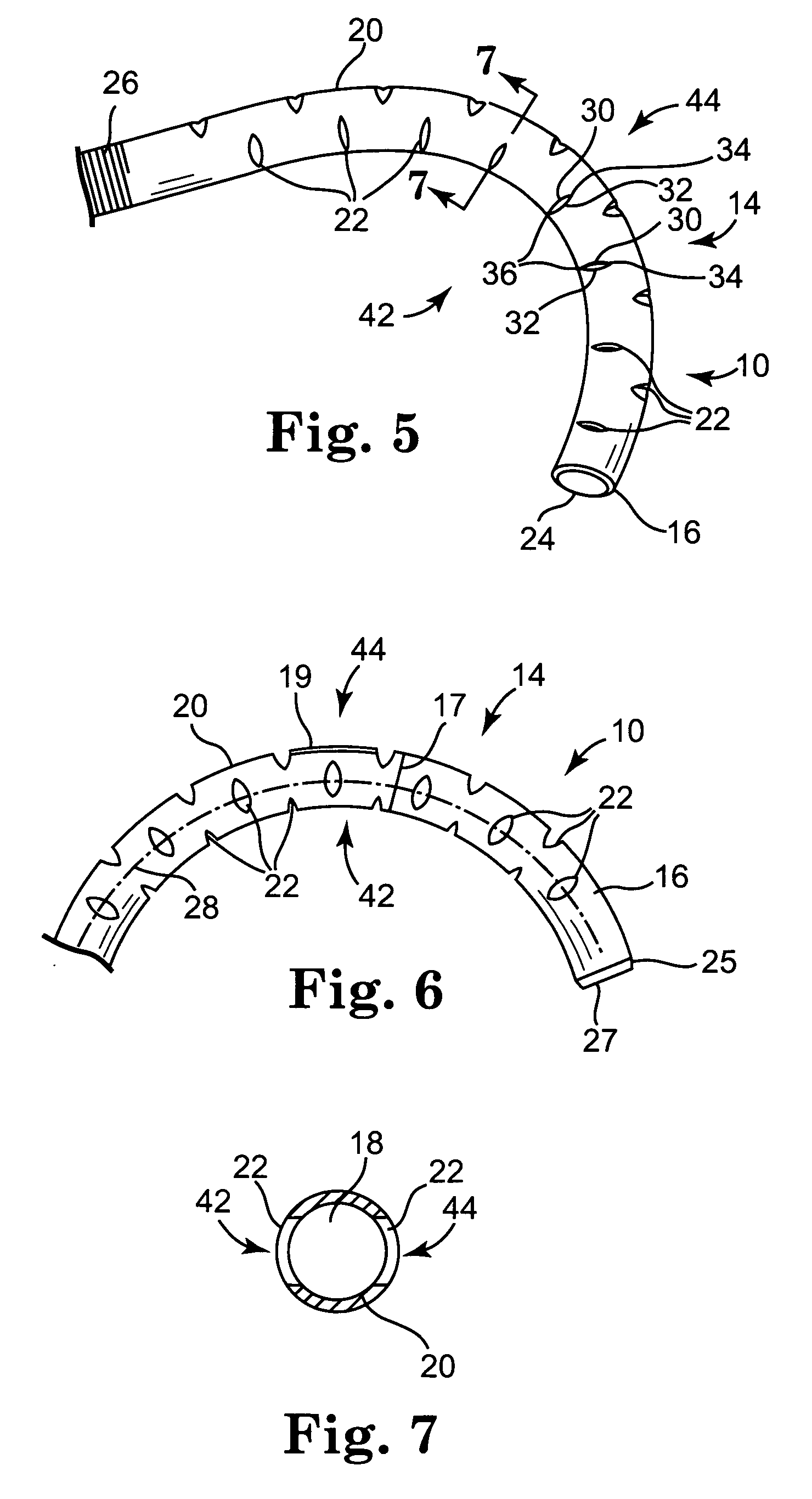
[0041] Referring to FIG. 3, a catheter or cannula, shown as, but not limited to, venous cannula 10 has a body 21 with a proximal end 12, a distal end 14 and a tip 16. The tip 16 is located at the distal end 14 of the cannula 10 and a lumen 18 formed in the body 21 extends through the cannula 10 from the proximal end 12 to the tip 16. The wall 20 has a circumference 17.

[0042] The lumen 18 may be open at the proximal end 12 to be connected to a cardiac bypass system such as a heart-lung machine. I...


PUM


Abstract

A cannula has a body with a proximal end and a distal end and a tip on the distal end. The tip has an outer wall defining a lumen opening at the end of the tip and extending to the proximal end of the cannula. The tip further comprises one or more ribs extending into the lumen to support the outer wall from kinking when the cannula is flexed. The outer wall has a inner surface defining the lumen and a plurality of non-circular apertures formed in the tip extending into the lumen. The apertures having a major axis and a minor axis. The major axis aligned in relation to a circumference of the outer wall to prevent puckering or buckling when the tip is bent. This alignment is also designed to support the outer wall from kinking when the tip is bent.

Description

CROSS-REFERENCE TO RELATED APPLICATIONS [0001] This application claims the benefit of U.S. Provisional Patent Application No. 60 / 487,393, filed Jul. 15, 2003 and further, a continuation-in-part of U.S. non-provisional application No. 10 / 619,932, filed Jul. 15, 2003 both of which are incorporated herein by reference in their entirety.FIELD OF THE INVENTION [0002] The present invention relates to a medical cannula. In particular, the present invention relates to a cannula having apertures that are buckle resistant. BACKGROUND OF THE INVENTION [0003] During cardiac surgery, circulation of blood through a patient's body may be maintained by connecting the patient to an extracorporeal system, such as a heart-lung machine. The heart-lung machine adds oxygen to and removes carbon dioxide from the blood, heats or cools the blood, and provides impetus to the blood to cause the blood to circulate through the patient's vascular system. [0004] Connecting a patient to an extracorporeal system is...

Claims


Application Information

Patent Timeline
Patent Type & Authority Applications(United States)
IPC IPC(8): A61M25/00
CPCA61B17/3421A61M25/0023A61M1/3659A61M2025/004A61M25/003
Inventor ENGEL, REBECCA LYNNSANDMORE, DONALD R.DEWINDT, DAVID BRUCESHOREY, FREDERICK ALAN JR.WESTON, DAVID EDWARD
Owner MEDTRONIC INC
Why Eureka
Try Eureka