Occlusion catheter with frictional valve

Inactive Publication Date: 2005-02-10
MEDTRONIC VASCULAR INC
View PDF19 Cites 16 Cited by
  • Summary
  • Abstract
  • Description
  • Claims
  • Application Information

AI Technical Summary

Benefits of technology

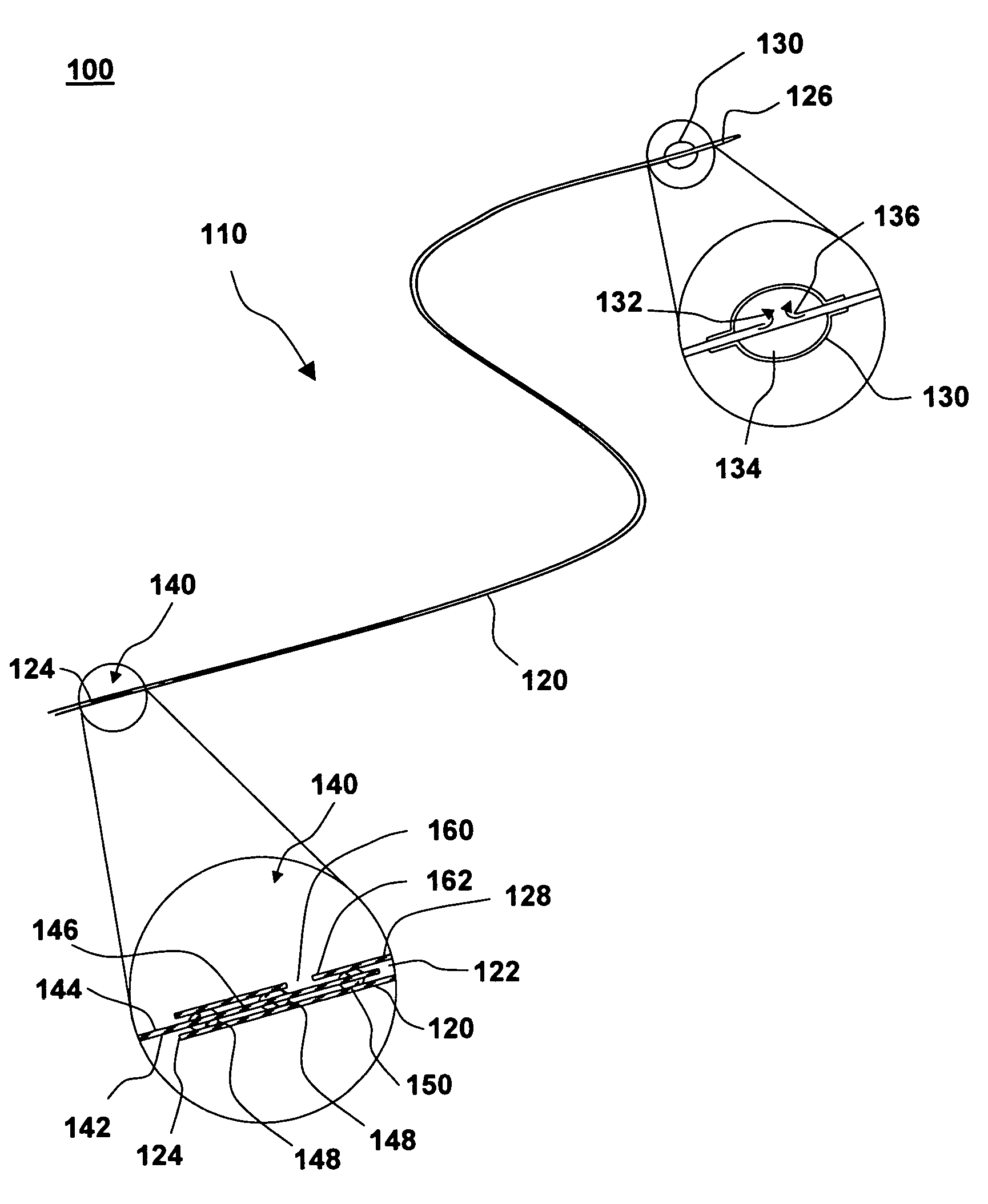
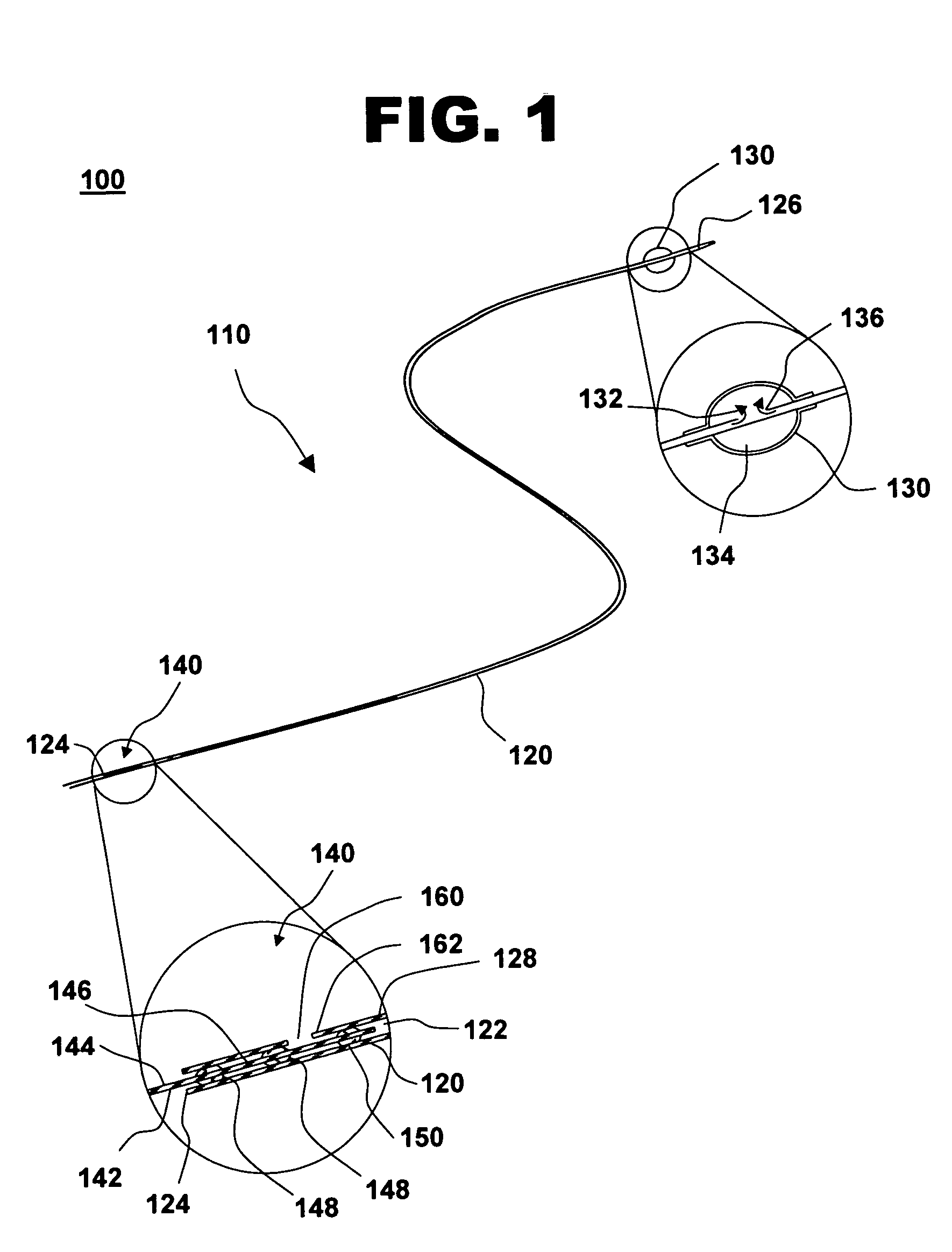
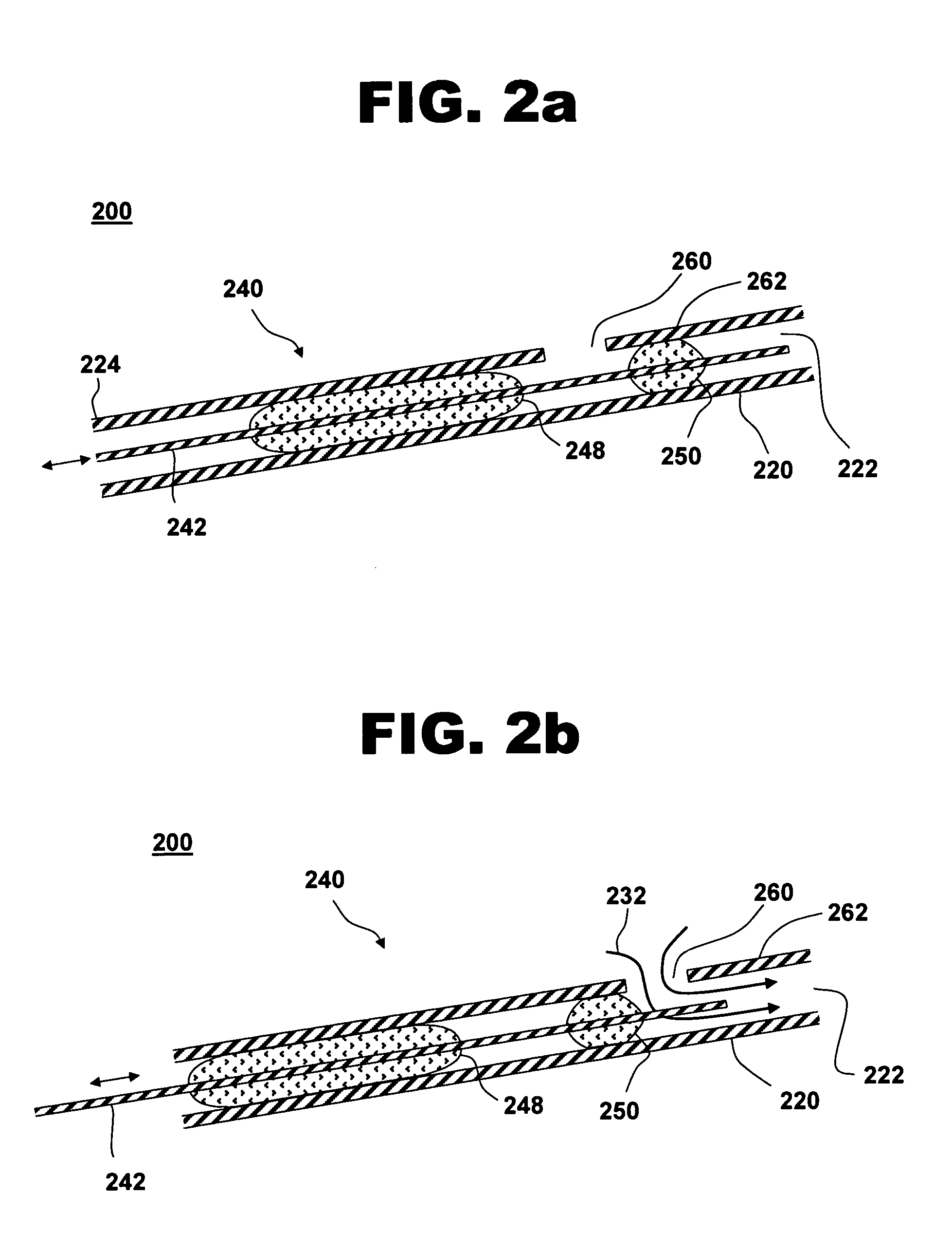
[0024] Another aspect of the invention is a system for treating a vascular condition, including a hollow guidewire with a central lumen and at least one longitudinally oriented slot formed in a sidewall of the hollow guidewire, an occlusion balloon attached proximate to a distal end of the hollow guidewire, and a frictional valve having a portion of a core wire positioned within a proximal end of the hollow g

Problems solved by technology

Unfortunately, the intravascular procedures associated with these devices may result in particles being dislodged while the restriction is dilated or cut.
Such disl

Method used


Image

  • Occlusion catheter with frictional valve
  • Occlusion catheter with frictional valve
  • Occlusion catheter with frictional valve

Examples


second embodiment

[0056] Alternatively, a second embodiment illustrated in FIG. 3 may include a valve plug (not shown) mounted to core wire 342 distally of frictional plug 348 and operating cooperatively with an inflation hole (not shown) disposed distally of slots 364 to form a frictional valve in accordance with the invention.

first embodiment

[0057]FIG. 4 is a graph of a compliance characteristic for a frictional valve, in accordance with one embodiment of the present invention at 400. Valve compliance graph 400 corresponds to a frictional valve with a frictional plug adjacent to one or more longitudinally oriented slots in a hollow guidewire, such as the example shown in FIG. 3. Valve stiffness, or force required to translate core wire 342, is plotted versus the translational displacement of core wire 342, with frictional plug 348 moving along slot 364. The valve stiffness, the reciprocal of the valve compliance, is lowest when frictional plug 348 is centered along the length of longitudinally oriented slot 364 and increases as frictional plug 348 approaches the ends of slot 364. In contrast, a frictional valve without slots has a nominally constant valve stiffness or valve compliance with respect to translations of the core wire that has one or more frictional plugs. FIG. 4 shows the longitudinal transition between ope...


PUM


Abstract

A system for treating a vascular condition, including a hollow guidewire having a central lumen and an inflation hole formed in a sidewall of the hollow guidewire, an occlusion balloon attached proximate to a distal end of the hollow guidewire, and a frictional valve. The frictional valve includes a portion of a core wire positioned within a proximal end of the hollow guidewire, a valve plug attached to the core wire, and at least one frictional plug attached to the core wire proximal to the valve plug. Flow of fluid through the central lumen of the hollow guidewire is controlled by axial translation of the core wire to position the valve plug with respect to the inflation hole, while the frictional plug provides a tailored valve compliance characteristic.

Description

FIELD OF THE INVENTION [0001] This invention relates generally to balloon catheters and guidewire deployment of catheter-based treatment tools. More specifically, the invention relates to an occlusion catheter with a frictional valve mechanism. BACKGROUND OF THE INVENTION [0002] The successful implementation of balloon-catheter procedures involves controlling the flow of fluid to a balloon of a catheter or a treatment area in a vessel of a human body. Medical balloon catheters have been proven efficacious in treating a wide variety of blood vessel disorders such as intravascular restrictions due to atherosclerosis or restenosis. Balloon angioplasty, or percutaneous transluminal coronary angioplasty (PTCA), is commonly used to alleviate stenotic lesions in blood vessels, thereby reducing the need for heart bypass operations. [0003] Balloon catheter and guidewire-deployed treatment systems are used to temporarily occlude a vessel in the coronary vasculature during diagnostic and inter...

Claims


Application Information

Patent Timeline
IPC IPC(8): A61F2/958A61M39/00A61M25/01A61M25/09A61M29/00
CPCA61M25/09025A61M25/10A61M2025/1052A61M2025/09008A61M25/1018A61M25/10185A61M25/10186
Inventor SATER, GHALEB A.
Owner MEDTRONIC VASCULAR INC
Why Eureka
Try Eureka