Balloon Closure Device

a balloon closure and puncture technology, applied in the field of system and method of sealing punctures, can solve the problems of time-consuming and expensive procedures, requiring as much as an hour of medical professionals' time, uncomfortable for patients, etc., and achieve the effect of effectively occluding the puncture, preventing the dislodgment of the balloon closure device, and puncture tra

Active Publication Date: 2019-01-17
BLUMENTHAL STEVEN JAY
View PDF17 Cites 6 Cited by
  • Summary
  • Abstract
  • Description
  • Claims
  • Application Information

AI Technical Summary

Benefits of technology

[0021]Any of the aforementioned embodiments may be used to deliver the balloon closure device with similar subsequent steps as described below. The balloon closure device may be introduced into the puncture with the occlusion and anchor balloons in a collapsed state until the expandable member is disposed within the body lumen. Preferably not, but if necessary, for example, the system may be introduced through a lumen of a peel-away introducer sheath or other tubular member previously placed in the puncture. In either embodiment, the anchor catheter may be advanced more distally than the occlusion catheter, to enter the body lumen. Once, intraluminal position is confirmed, fluid may be introduced into the anchor catheter to expand the coupled anchor balloon to an expanded state. The anchor catheter may be at least partially withdrawn from the puncture until the anchor balloon engages tissue at a location where the puncture penetrates a wall of the body lumen, thereby substantially sealing the puncture from the body lumen. While pull-back tension is applied to the anchor balloon that is “anchored” in the body lumen, the occlusion catheter may be advanced ...

Problems solved by technology

This procedure, however, may be time consuming and expensive, requiring as much as an hour of a medical professional's time.
It is also uncomfortable for the patient, and may require the patient to remain immobilized in the operating room, catheter lab, or holding area.
In addition, a risk of hematoma exists from bleeding before hemostasis occurs.
The disclosed plug, however, may be difficult to position properly with respect to the vessel, which may be significant since it is generally undesirable to expose the col...

Method used


Image

  • Balloon Closure Device
  • Balloon Closure Device
  • Balloon Closure Device

Examples


Embodiment Construction

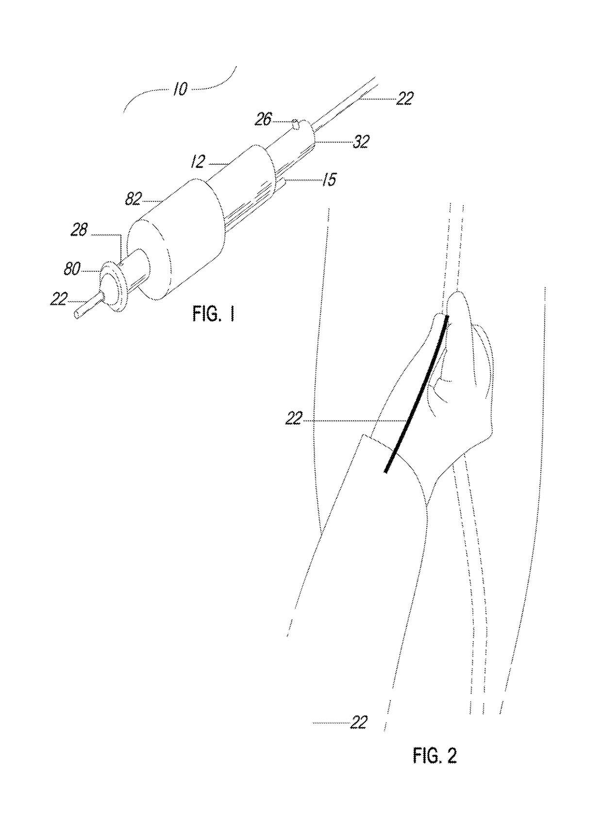
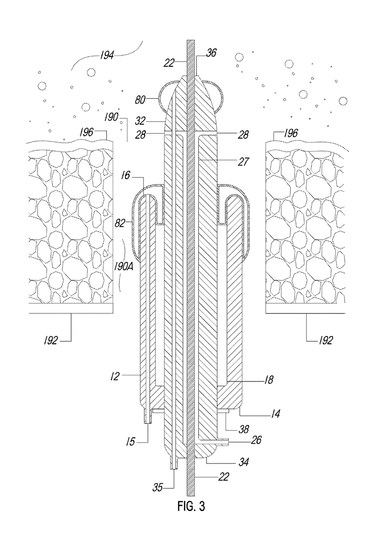
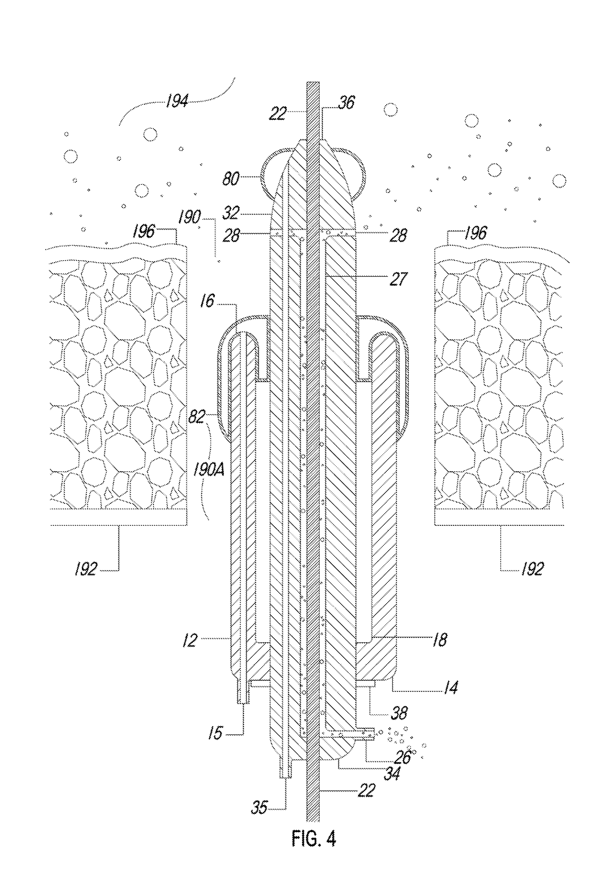
[0045]Referring now in greater detail to the various figures of the drawings wherein like reference characters refer to like parts. Turning to the drawings, FIGS. 1-12, show a preferred embodiment of the system, referred to as the balloon closure device 10 for sealing a puncture extending through tissue and / or communicating with a body lumen. The puncture 190 includes not only the opening in the wall of the vessel but also the puncture tract 190A, i.e., the passageway in the tissue located between the vessel and the skin of the being formed when the vessel is punctured.

[0046]The balloon closure device 10 has particular utility when used in connection with intravascular procedures, such as angiographic dye injection, cardiac catheterization, balloon angioplasty and other types of recanalizing of atherosclerotic arteries, etc. since the balloon closure device 10 is designed to cause immediate hemostasis of the blood vessel, e.g., arterial, puncture. However, it is to be understood tha...


PUM


Abstract

A system for sealing a percutaneous puncture communicating with a blood vessel in a living being and method of use thereof. The system, referred to in the present embodiment, as a balloon closure device, includes an inner member, referred to as an anchor catheter, slidable within an outer member, referred to as an occlusion catheter, and separate expandable members, referred to as balloons, coupled to the distal ends of both the anchor and occlusion catheters. Also, incorporated into the distal end of the anchor catheter are blood vessel locator holes for determining the position of the blood vessel via the percutaneous puncture. The vessel locator includes means for enabling blood from the vessel to flow therethrough so that the position of the vessel can be rapidly determined. Once the balloon closure device has been extended into the puncture and the vessel has been located, the ballon closure device may be deployed. The anchor catheter and its balloon are located within the blood vessel, while the occlusion catheter and its balloon are located within the puncture tract leading to the vessel. Once the balloon closure device is positioned, hemostasis occurs rapidly, and the necessary components are locked in place.
A proximal end of the occlusion catheter includes a port for delivering fluid into the balloon, and a cylindrical lumen that communicates with the port. A proximal end of the anchor catheter includes a port for delivering fluid into the balloon, and a cylindrical lumen that communicates with the port. The anchor catheter may also include a cylindrical lumen to accommodate a guidewire. The balloon closure device is introduced like a standard sheath exchange. First, the existing sheath is removed over a guidewire. Next, the occlusion catheter coupled with an inner distally tapered anchor catheter/introducer is passed over the guidewire through the puncture, disposing the anchor catheter/introducer with its collapsed balloon in the vessel lumen, while the occlusion catheter with its collapsed balloon is disposed in the puncture tract. Once vessel lumen location is confirmed, fluid is introduced into the anchor catheter port, inflating the anchor balloon. The anchor balloon is withdrawn to seal the puncture. The occlusion catheter is advanced to the distal end of the puncture tract just outside the vessel wall, and abutting the inflated anchor balloon. Fluid is introduced into the occlusion catheter port, inflating the occlusion balloon, to both occlude the puncture and secure the occlusion catheter in the puncture tract. The anchor balloon is then deflated, allowing the anchor catheter/introducer to be withdrawn into the puncture tract and removed. Once hemostasis is confirmed, the guidewire is removed. After an interval, the occlusion balloon may be deflated to check for hemostasis. Once hemostasis is confirmed, the remaining occlusion catheter may be removed, leaving nothing behind but the body's own hemostatic plug.

Description

FIELD OF THE INVENTION[0001]The present invention relates generally to a system and methods for sealing punctures in a body, and more particularly, to a system and methods for sealing a percutaneous puncture extending from a patient's skin through tissue into a blood vessel or other body lumen.BACKGROUND OF THE INVENTION[0002]A system and methods are known for accessing a patient's vasculature percutaneously, e.g., to perform a procedure within the vasculature, and for sealing the puncture that results after completing the procedure. For example, a hollow needle may be inserted through a patient's skin and overlying tissue into a blood vessel. A guide wire may be passed through the needle lumen into the blood vessel, whereupon the needle may be removed. An introducer sheath may then be advanced over the guide wire into the vessel, e.g., in conjunction with or subsequent to one or more dilators.[0003]A catheter or other device may be advanced through the introducer sheath and over th...

Claims


Application Information

Patent Timeline
IPC IPC(8): A61B17/00
CPCA61B17/0057A61B2017/00623A61B90/08A61B2017/00884A61B2017/0061A61B2090/0811A61B2017/00336A61B2017/00557A61B2017/00654A61B2017/00672A61B2017/00676
Inventor BLUMENTHAL, STEVEN JAY
Owner BLUMENTHAL STEVEN JAY
Why Eureka
Try Eureka