
Emulation of a programmable hardware element

a hardware element and emulator technology, applied in the field of program debugging, can solve the problems of inefficient or feasible for many users to make a small change and wait, and the likelihood of a new product to contain a “bug” in each compile is high, and the effect of wasting tim

Active Publication Date: 2005-02-10
NATIONAL INSTRUMENTS
View PDF8 Cites 35 Cited by
  • Summary
  • Abstract
  • Description
  • Claims
  • Application Information

AI Technical Summary

Benefits of technology

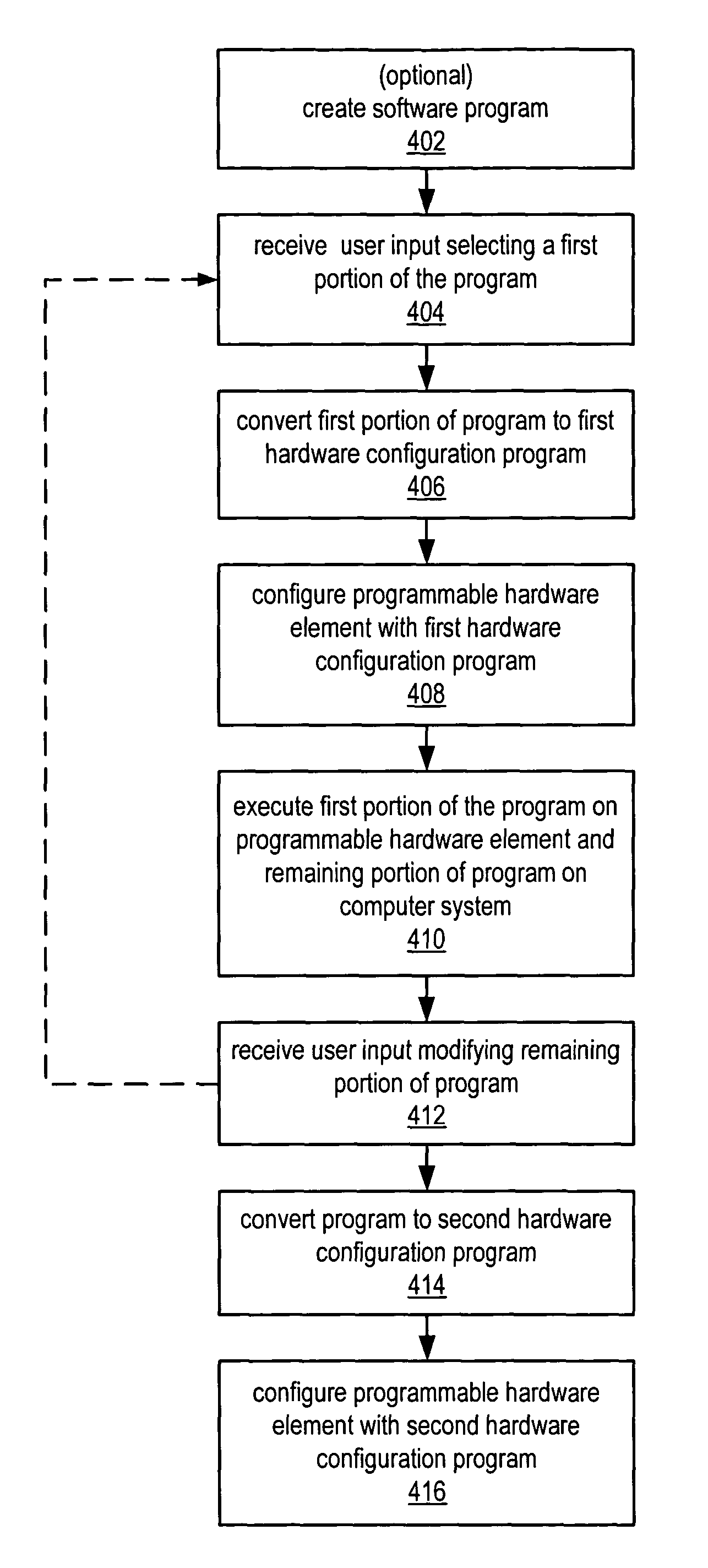
In one embodiment, determining the test feed-through configuration may include determining a plurality of pre-compiled hardware configuration program components, and assembling the plurality of pre-compiled hardware configuration program components, thereby generating the test feed-through configuration. This use of pre-compiled hardware configuration program components may substantially decrease the time required to perform the debug cycle in that long compile times may be substantially avoided. In another embodiment, determining the test feed-through configuration may include generating a test feed-through software program based on said analyzing, and compiling the test feed-through software program, thereby generating the test feed-through configuration.
Thus, the techniques described herein may be used to improve the emulation performance of some applications during the debugging process. Typical applications include some portions of logic that are relatively static and fixed, and other portions that are more likely to change during development. For example, the VI for a motion controller may contain a quadrature decoder to monitor position. This is a relatively straightforward block that is unlikely to change during the course of development. It also tends to work poorly when emulated in software due to performance reasons. Thus, a custom emulation personality that incorporates user tagged portions of the application diagram (in this case the quadrature decoder) may be deployed onto the hardware, providing a more realistic emulation of the final application, and possibly allowing additional testing not possible with the software implementation of the user logic. The other portions of the application, such as the actual PID loop, may still run in software to speed development. The user can iterate on this process and generate a new emulation personality that includes additional functionality as each portion of the design becomes stable.

Problems solved by technology

Often, the field signals may comprise high common-mode voltages, ground loops, or voltage spikes that often occur in industrial or research environments which could damage the computer system.
Because most computer programs and many programmed hardware devices contain thousands of lines of code, almost any new product is likely to contain “bugs”.
However, depending upon the complexity of the program and / or the programmable hardware element, the compilation time may range from minutes to hours or even tens of hours.
This is inefficient as each compile can take substantial time depending upon the application.
Thus, the difficulty with this approach when targeting hardware is due to compile times. Typical compile times for creating software in LabVIEW are measured in seconds, or milliseconds, whereas typical compile times for programming hardware in LabVIEW range from minutes to hours.
Thus, it is not efficient or feasible for many users to make a small change and wait hours to see the results.
Such compile times may make debugging the program substantially difficult, e.g., tedious and error prone, in that the typical iterative debug cycle of modifying the program, compiling the modified program, and executing the compiled program on the target system may require so much time as to make the debug process unfeasible or inordinately expensive.
This difficulty may be particularly apparent in the field (as opposed to in a research, production, or manufacturing development context), where a user may need to development an application program under time constraints.
Additionally, the types of information available to the user in debugging the program once it has been deployed to the programmable hardware element is generally extremely limited, making the debugging process less effective.
However, in some cases portions of the emulated functionality may not be sufficiently accurate in representing the operation of that portion of the program implemented on the programmable hardware element, or may have a substantially lower performance.

Method used


Image

  • Emulation of a programmable hardware element
  • Emulation of a programmable hardware element
  • Emulation of a programmable hardware element

Examples


Embodiment Construction

Incorporation by Reference

The following U.S. Patents and patent applications are hereby incorporated by reference in their entirety as though fully and completely set forth herein.

U.S. patent application Ser. No. 10 / 055,691, titled “System and Method for Debugging a Software Program” filed Oct. 29, 2001, whose inventors are Hugo A. Andrade, Brian Keith Odom, Cary Paul Butler, Joseph E. Peck and Newton G. Petersen.

U.S. patent application Ser. No. 10 / 058,150, titled “Reconfigurable Measurement System Utilizing a Programmable Hardware Element and Fixed Hardware Resources” filed Oct. 29, 2001, whose inventors are Brian Keith Odom, Joseph E. Peck, Hugo A. Andrade, Cary Paul Butler, James J. Truchard, Newton Petersen and Matthew Novacek.

U.S. patent application Ser. No. 09 / 229,695 titled “Reconfigurable Test System” filed on Jan. 13, 1999, whose inventors are Arthur Ryan, Hugo Andrade, and Brian Keith Odom, which is now U.S. Pat. No. 6,322,249.

U.S. Provisional Patent Application...


PUM


Abstract

System and method for debugging a program intended for execution on a programmable hardware element (PHE) to perform a function. A first portion of the program is converted into a first hardware configuration program (HCP) deployable on the PHE, where a remaining portion is to be debugged by a user. The PHE is configured with the first HCP, and the program executed, including the PHE executing the first portion of the program, and the computer system executing the remaining portion, which is then analyzed and debugged in response to being executed, and user input received modifying the remaining portion to debug the remaining portion. The method is repeated, where in each iteration the first portion is a successively larger portion of the program. After being debugged, the program is converted into a second HCP deployable on the PHE to perform the function, and the PHE configured with the second HCP.

Description

FIELD OF THE INVENTION The present invention relates to program debugging, and particularly to debugging programs intended for execution on a programmable hardware element, such as a field programmable gate array. DESCRIPTION OF THE RELATED ART Scientists and engineers often use measurement or instrumentation systems to perform a variety of functions, including laboratory research, process monitoring and control, data logging, analytical chemistry, test and analysis of physical phenomena, and control of mechanical or electrical machinery, to name a few examples. An instrumentation system typically includes transducers and other detecting means for providing “field” electrical signals representing a process, physical phenomena, equipment being monitored or measured, etc. Exemplary transducers include thermocouples, strain gauges, pressure sensors, microphones and cameras. As one example, detectors and / or sensors are used to sense the on / off state of power circuits, proximity switch...

Claims


Application Information

Patent Timeline
IPC IPC(8): G06F9/44
CPCG06F11/3648
Inventor PECK, JOSEPH E.
Owner NATIONAL INSTRUMENTS
Learn More