Air conditioning apparatus using variable displacement compressor

Inactive Publication Date: 2005-02-17
SANDEN CORP
View PDF13 Cites 11 Cited by
  • Summary
  • Abstract
  • Description
  • Claims
  • Application Information

AI Technical Summary

Benefits of technology

[0006] According to one mode of the present invention, there is obtained an air conditioner provided with a refrigerant circulation circuit including a variable capacity compressor, said air conditioner characterized by comprising collision force detecting means for detecting a collision force of a refrigerant flowing in said refrigerant circulation circuit to produce a collision force detection value, and discharge capacity control means for controlling a discharge capacity of said variable capacity compressor by referring to said collision force detection value.
[0007] According to another mode of the present invention, there is obtained an air conditioner provided with a refrigerant circulation circuit

Problems solved by technology

Such a pressure transmitting passage makes intric

Method used


Image

  • Air conditioning apparatus using variable displacement compressor
  • Air conditioning apparatus using variable displacement compressor
  • Air conditioning apparatus using variable displacement compressor

Examples


Example

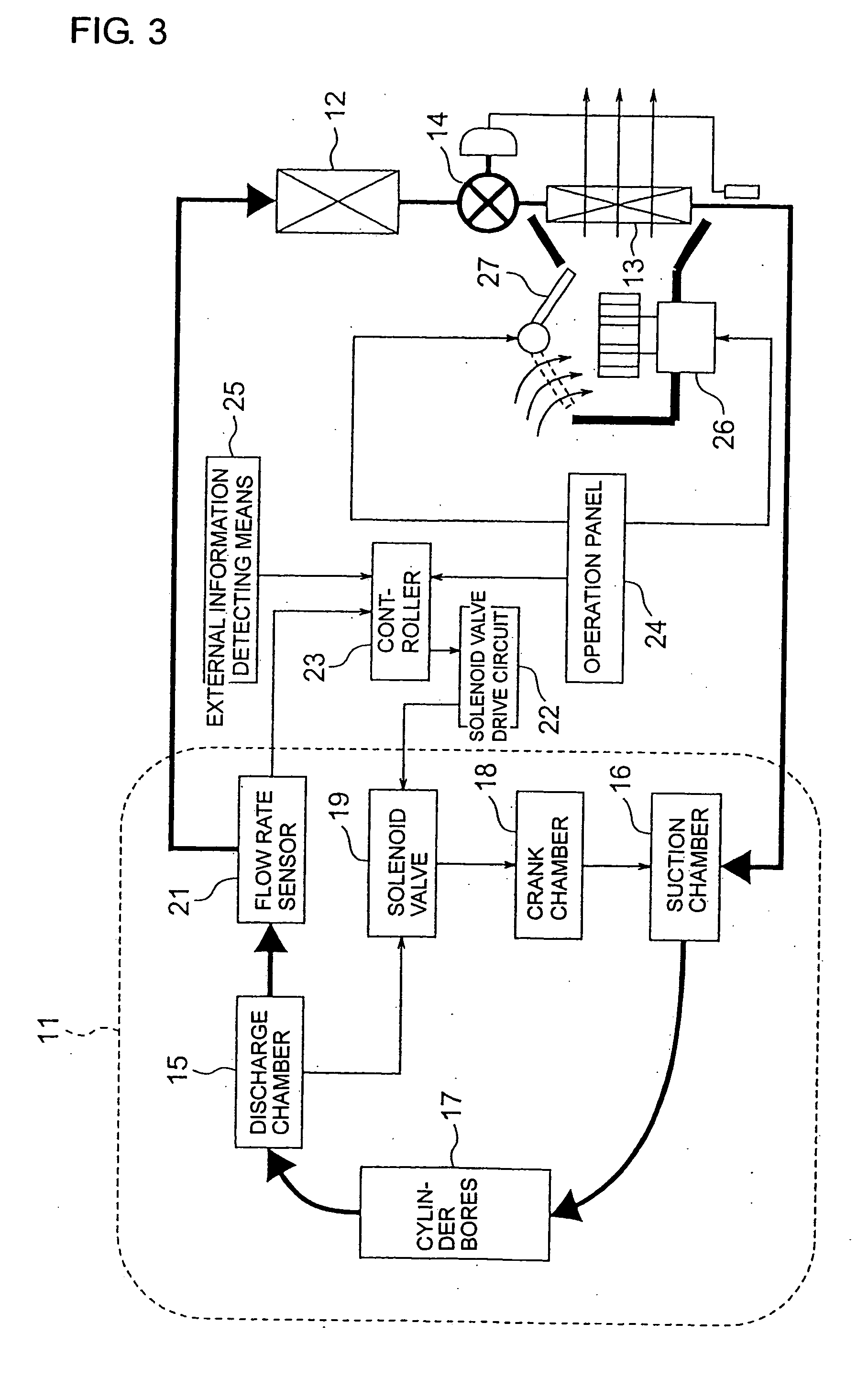
[0023] Referring now to FIG. 3, the whole of an air conditioner according to a first embodiment of the present invention will be described.

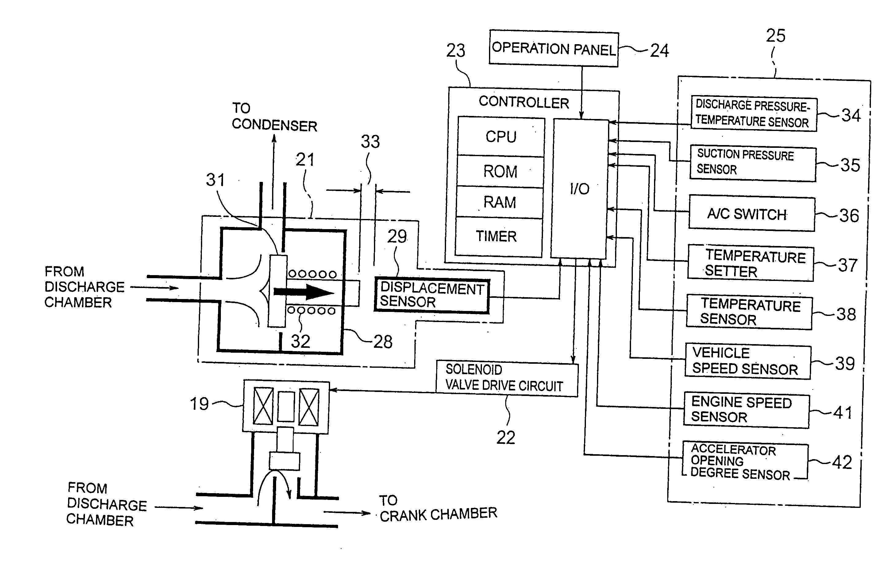
[0024] An air conditioner in FIG. 3 is a vehicle air conditioner and includes a refrigerant circulation circuit comprising a variable displacement swash plate compressor 11 and an external refrigerant circuit. The external refrigerant circuit comprises a condenser 12 connected to the discharge side of the compressor 11, an evaporator 13 connected to the suction side of the compressor 11, and an expansion valve connected between the condenser 12 and the evaporator 13.

[0025] As is well known, the variable displacement swash plate compressor 11 comprises a discharge chamber 15 connected to the condenser 12, a suction chamber 16 connected to the evaporator 13, cylinder bores 17 interposed between the discharge chamber 15 and the suction chamber 16, a crank chamber 18 provided therein with a crank mechanism (not shown) for a cam (swash plate etc.) f...

Example

[0034] Shifting to FIG. 5, the whole of an air conditioner according to a second embodiment of the present invention will be described. Those portions that are the same as FIG. 3 are given the same reference symbols to thereby omit description thereof.

[0035] The air conditioner in FIG. 5 is provided with a control valve 51 between a discharge chamber 15, and a condenser 12 and a crank chamber 18, instead of the solenoid valve 19 and the flow rate sensor 21 in the air conditioner in FIG. 3. The control valve 51 serves to adjust the flow rate of the refrigerant headed toward the crank chamber 18 from the discharge chamber 15 by utilizing an electromagnetic force and balancing between such an electromagnetic force and a force caused by the flow of the discharged refrigerant from the discharge chamber 15, to thereby control the pressure in the crank chamber 18 and, according to the well known principle, serves to change the discharge capacity of the variable displacement swash plate co...


PUM


Abstract

In an air conditioner provided with a refrigerant circulation circuit having a variable displacement compressor (11), there is provided a flow rate sensor (21) for detecting a collision force of a refrigerant flowing in the refrigerant circulation circuit to produce a collision force detection value. A discharge capacity of the variable displacement compressor is controlled referring to the collision force detection value. It may also be possible to control a discharge capacity such that a valve portion serving to introduce a discharged refrigerant into a crank chamber is applied with a collision force of the refrigerant and an electromagnetic force in opposite directions and, when the collision force is greater than the electromagnetic force, the valve portion is opened to cause the collision force to approach the electromagnetic force.

Description

TECHNICAL FIELD [0001] The present invention relates to an air conditioner provided with a refrigerant circulation circuit including a variable capacity compressor and, in particular, relates to a control of a discharge capacity. BACKGROUND ART [0002] In an air conditioner of this type, it is important to detect and control a circulation amount of refrigerant flowing in a refrigerant circulation circuit, i.e. a refrigerant circulation amount. Japanese Patent Application Publication No. 2001-140767, for example, discloses an air conditioner wherein two pressure monitoring points are provided in a refrigerant circulation circuit including a variable capacity compressor, and a refrigerant circulation amount is controlled using a correlation between a differential pressure between those pressure monitoring points, and the refrigerant circulation amount. Specifically, the differential pressure between the pressure monitoring points is detected, and a discharge capacity of the variable ca...

Claims


Application Information

Patent Timeline
IPC IPC(8): F04B49/00F04B27/14F04B27/18F04B49/06F25B1/00F25B49/02
CPCF04B27/1804F04B2027/1827F04B2027/185F04B2027/1854F25B2700/21152F25B2700/04F25B2700/13F25B2700/1931F25B2700/1933F25B49/022
Inventor OCHIAI, YOSHIHIRO
Owner SANDEN CORP
Why Eureka
Try Eureka