By-pass pressure regulator

a pressure regulator and bypass technology, applied in mechanical equipment, transportation and packaging, functional valve types, etc., can solve the problems of compromising the effective operation of the valve, the design and manufacture of pressure regulating valves is difficult, and the seat wear and leakage of the valve may also be difficult, so as to facilitate smoother and more accurate operation of the valve.

Inactive Publication Date: 2005-02-17
TECUMSEH PROD CO
View PDF15 Cites 6 Cited by
  • Summary
  • Abstract
  • Description
  • Claims
  • Application Information

AI Technical Summary

Benefits of technology

[0012] The first passages of the valve member may be oriented at an angle with respect to the longitudinal axis of the valve. In this manner, the first passages have an elliptically-shaped interface with the internal wall of the valve member such that, upon movement of the valve member toward the second position, the first passages are brought into gradual communication with the recessed portion of the valve body to facilitate smoother and more accurate operation of the valve responsive to fluid pressure.

Problems solved by technology

Problematically, O-rings, gaskets, or other seals between the valve member and valve body may wear out over time, possibly leading to leakage and thereby compromising effective operation of the valve.
Similarly, the valve seats may also wear out or leak over time.
Further, pressure regulating valves have been difficult to design and manufacture such that the valves quickly open responsive to a controlled, predetermined pressure threshold to thereby regulate the fluid pressure within the system at a precise, constant level.

Method used


Image

  • By-pass pressure regulator
  • By-pass pressure regulator
  • By-pass pressure regulator

Examples


Embodiment Construction

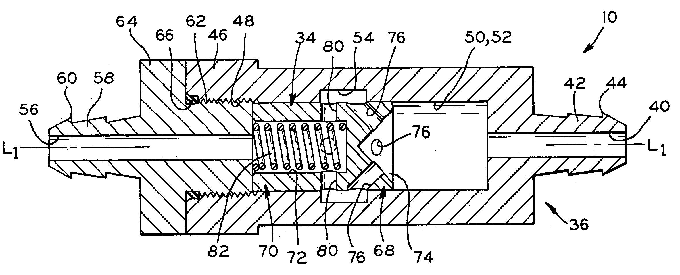
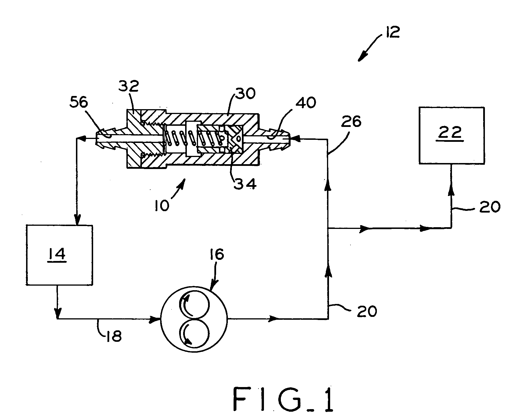
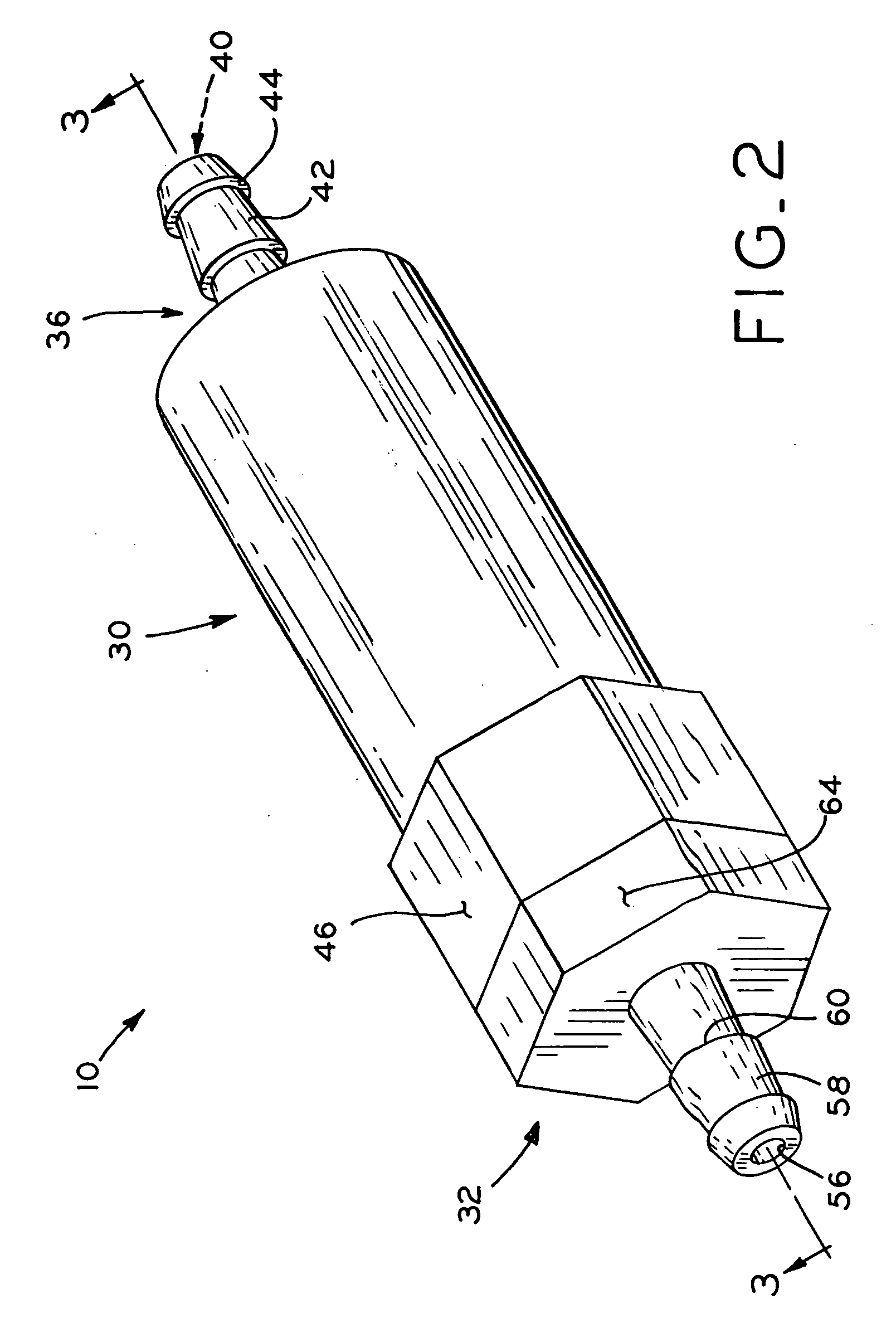
[0027] Referring to FIG. 1, an exemplary fluid system is shown, which includes a pressure regulating valve 10 in accordance with the present invention. In particular, the fluid system is exemplified herein as fuel injection system 12 for an internal combustion engine. Although pressure regulating valve 10 is described herein with reference to fuel injection system 12 which includes fuel as the working fluid, one of ordinary skill in the art will appreciate that the pressure regulating valve 12 of the present invention may be used with any type of fluid system which includes a pressure-responsive valve to regulate the pressure of a working fluid therein.

[0028] In FIG. 1, fuel injection system 12 includes fluid reservoir 14, such as a gas tank, which contains a supply of combustible fuel such as gasoline. Pump 16 draws fuel from reservoir 14 through line 18. Pump 16 may be a gerotor pump, reciprocating pump, peristaltic pump, or another type of fluid pump. Pump 16 supplies fuel under...


PUM


Abstract

A pressure regulating valve which is responsive to pressure within a fluid system and operable to relieve pressure within the fluid system if same exceeds a predetermined pressure threshold, allowing the regulated pressure in the system to be held to a very accurate level. In particular, the valve includes a valve body having an inlet, an outlet, and a valve chamber which includes a recessed portion. A valve member is movable within the valve chamber, and includes at least one first passage in fluid communication with the inlet at least one second passage in fluid communication with the outlet. The valve member is movable within the valve body responsive to fluid pressure between first and second positions. In the first position, at least one of the first and second passages is not aligned with the recessed portion, such that fluid cannot flow through the valve. In the second position, at least a portion of each of the first and second passages is aligned with the recessed portion, such that fluid may flow from the inlet to the outlet through the first passage, the recessed portion, and the second passage.

Description

BACKGROUND OF THE INVENTION [0001] 1. Field of the Invention [0002] The present invention relates to by-pass pressure regulators for fluid systems, which prevent the fluid pressure within the fluid system from exceeding a desired predetermined level. [0003] 2. Description of the Related Art [0004] Many fluid systems include a closed or semi-closed fluid loop, in which a pump draws fluid from a fluid reservoir and supplies same to a desired location, followed by return of at least a portion of the fluid back to the fluid reservoir. Other, non-loop fluid systems include a pump which supplies fluid from a fluid source to a desired location where most or all of the fluid is used or consumed. [0005] One example of a closed loop fluid system is a fuel injection system for an internal combustion engine. In this system, a pump draws a combustible fuel, such as gasoline, from a fuel tank and supplies the fuel under pressure to one or more fuel injectors which inject the fuel into the combust...

Claims


Application Information

Patent Timeline
Patent Type & Authority Applications(United States)
IPC IPC(8): F16K15/02
CPCF16K15/026Y10T137/7925
Inventor RADO, GORDON E.
Owner TECUMSEH PROD CO
Why Eureka
Try Eureka