AC permanent magnet motor

a permanent magnet motor and alternating current technology, applied in the direction of rotating magnets, magnetic circuit rotating parts, synchronous machines with stationary armatures, etc., can solve the problems of increasing the cost of electric power consumption of stators. , to achieve the effect of reducing magnetic resistance, facilitating smooth and continuous rotation, and facilitating operation

Active Publication Date: 2020-02-18
ZHANG XIAN
View PDF12 Cites 4 Cited by
  • Summary
  • Abstract
  • Description
  • Claims
  • Application Information

AI Technical Summary

Benefits of technology

[0004]The technical solution provided by the present invention is an AC permanent magnet motor, including a stator and a rotor as one part and an external controller as the other part. Some cable troughs and some cores are machined on a silicon steel sheet laminated core of the stator of the AC permanent magnet motor. Same grooves are provided inside the cores, and same winding coils are inserted into the cable troughs. Surface magnetic polarities of permanent magnets mounted in grooves of silicon steel cores of two same coils that are immediately adjacent to each other are different from each other. One single-phase power source is supplied to one group of coil units. The coil unit includes an integer multiple of at least two same stator cores and permanent magnets in the grooves. If a two-layer coil is inserted into each cable trough, the coil unit further includes three same cable troughs and four same coils. Among the four coils, one side of each of two coils is inserted into the cable trough between two cores, forming a two-layer winding in the cable trough. The other two coils are respectively inserted into the other two cable troughs that are adjacent to the two cores, forming one-layer windings in the other two cable troughs, the other winding is formed by inserting a corresponding coil of another coil unit that is immediately adjacent to the coil unit, forming two-layer windings in the other two cable troughs, and so on, so that windings of a whole stator coil are inserted. For the two coils in the coil unit, one is electrified by a forward current, and the other is electrified by a reverse current, so that polarities of electromagnetic fields respectively generated in the two coils are also opposite. Polarities of permanent magnets mounted in the two coils need to be the same as the polarities of the electromagnetic fields of the coils respectively, and shapes, dimensions, and magnetic parameters of the permanent magnets also need to be the same, similar to that in two opposite DC electromagnetic coils, permanent magnets having polarities respectively the same as those of the two coils are mounted respectively, that is, a reference DC electromagnet. In this way, a new compound magnetic field generated because of homopolarity between an electromagnetic field of each coil and a constant magnetic field is enhanced due to a magnetic field superposition principle. Compared with an original single magnetic field, the compound magnetic field is enhanced, and the electromagnetic field can also magnetize and protect the permanent magnet, so that the permanent magnet would not be demagnetized. Some such combinations of two same coils respectively electrified by a forward or reverse current and cores form a coil unit. 2N same coil units form an in-phase coil, and every three in-phase coils form a stator three-phase coil where A+, B+, C+, A−, B−, C− and O lines are combined in a positive-negative correspondence manner. Some integer multiples of same three-phase coils form a complete stator coil of the motor.
[0010]The AC permanent magnet motor having the structure with the fixed hub and the inner rotating pivot includes some compound magnetic heads in coils of some cable troughs on the silicon steel laminated sheet body of the stator, a main shaft, a silicon steel laminated sheet body on the rotor, and the rotor including a squirrel-cage framework on the rotor, the recessed permanent magnet, and the inner pivot. The rotor is separated from the surface of the permanent magnet of the stator by an air gap. The main shaft is mounted in the center of the inner pivot of the rotor, and bearings are mounted at two ends of the inner pivot. In addition, the inner pivot is connected to the stator hub by using the bearings. A mesh structure in a fence shape on the surface of a compound magnetic head of a groove facilitates operation magnetic path smoothness of magnetic lines of the compound magnetic head including the permanent magnet. The motor stator has an even number of independent three-phase windings. Each winding includes some coils, and the coil windings are sequentially inserted into the cable troughs of the silicon steel laminated cores of the stator. The coil winding and the permanent magnets of the stator mounted in the grooves jointly form some pairs of compound magnetic heads of the stator. A compound magnetic head that is controlled during operation generates a controllable instant induction alternating electromagnetic field, to form a rotating magnetic field. In this case, the compound magnetic head has a function of changing the magnetic field, to reduce magnetic resistance and change the intensity of the constant magnetic field. Superposition or interference of magnetic fields of same polarities or different polarities of the compound magnetic head facilitates smooth and continuous rotation of the stator permanent magnet and the rotor permanent magnet that are correspondingly mounted on the rotary disc under an action force of magnetic energy.

Problems solved by technology

In a process of developing an entire system, new technical problems are constantly put forward.
Consequently, electricity consumption of the stator is not reduced, and heat dissipation of the stator consumes much energy, which may often result in a safety accident that a winding is burnt out due to overheating.
Costs for using the motor are low, and the failure rate is low.

Method used


Image

  • AC permanent magnet motor
  • AC permanent magnet motor
  • AC permanent magnet motor

Examples


Embodiment Construction

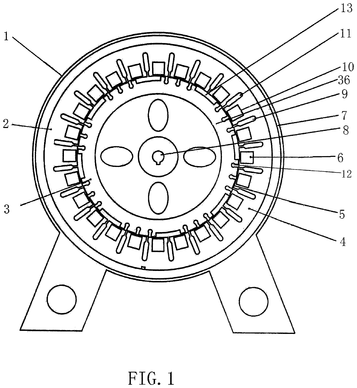
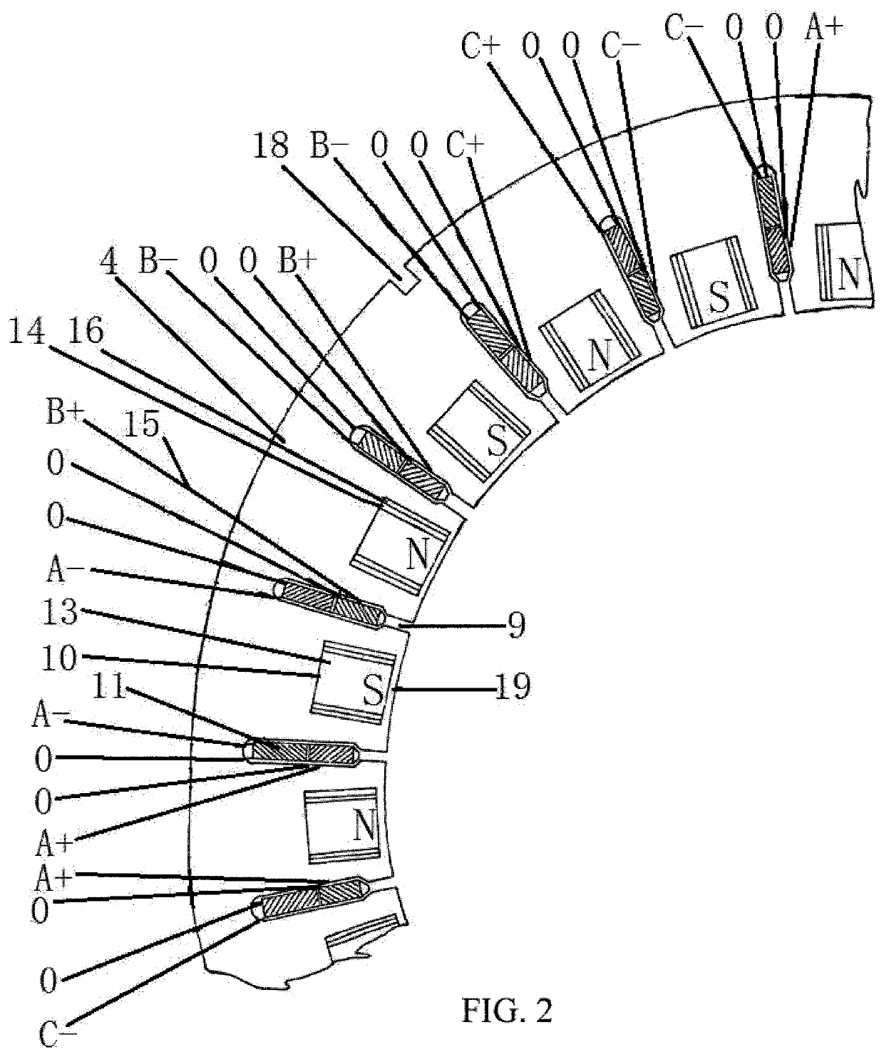
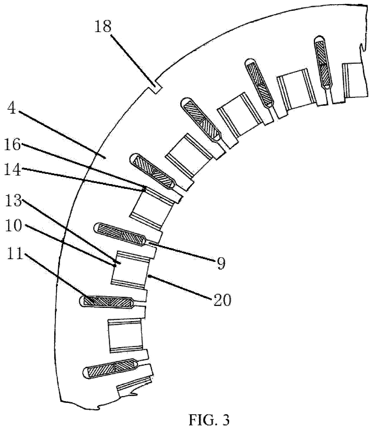
[0019]In embodiments of the present invention, with reference to FIG. 1, FIG. 2, FIG. 3, FIG. 4, FIG. 5, and FIG. 6, an AC permanent magnet motor 1 has a structure having an outer rotating hub and an inner stator or a structure having an outer fixed hub and inner rotating pivot. When sample design is researched, a wiring diagram of two-layer, cross, and short-distance windings that have 24 cable troughs and four poles in a most frequently used three-phase asynchronous motor is selected from a diagram set of commercially available motors. The AC permanent magnet motor 1 includes a stator 2 and a rotor 3 as one part and an external controller 30 as the other part. Some cable troughs 9 and some stator cores 4 are machined on the stator 2 of the AC permanent magnet motor. Same grooves 10 are provided inside the stator cores 4, and same winding coils 11 are inserted into the cable troughs 9. Surface magnetic polarities of permanent magnets 6 mounted in grooves 10 of stator cores of two s...


PUM


Abstract

The present invention discloses an alternating current (AC) permanent magnet motor, including a stator, a rotor, and a controller. Cable troughs and some same coil windings exist on a silicon steel sheet of a stator core. Grooves exist on the stator core, and stator permanent magnets are mounted in the grooves. The groove includes two types of grooves, namely, open grooves and enclosed grooves, and the two types of grooves are alternately laminated to form the stator core. A coil unit of the stator includes stator permanent magnets mounted in grooves of two stator cores and four same coils, and some same coil units form a three-phase stator coil. The rotor includes rotor cores, enclosed squirrel cages and rotor permanent magnets. The controller outputs a three-phase power source having a same positive and negative half sine-wave or step-wave pulse.

Description

BACKGROUNDTechnical Field[0001]The present invention relates to the field of magnetic energy conversion technologies of rare earth permanent magnets, to a permanent magnet motor indirectly converting magnetic energy into mechanical energy, and specifically, to an alternating current (AC) permanent magnet motor.Related Art[0002]Currently, it is urgently needed to develop a device that indirectly converts magnetic energy of a super permanent magnet made of a rare earth neodymium-iron-boron alloy into mechanical energy. In a process of developing an entire system, new technical problems are constantly put forward. In the market, although compared with a conventional motor, a permanent magnet motor having a rotor made of a rare earth permanent magnet obviously saves more electricity, an exciting coil is still used on a stator. Consequently, electricity consumption of the stator is not reduced, and heat dissipation of the stator consumes much energy, which may often result in a safety ac...

Claims


Application Information

Patent Timeline
Patent Type & Authority Patents(United States)
IPC IPC(8): H02K1/17H02K21/46H02K53/00H02K17/26H02K17/16H02K1/27H02K17/12
CPCH02K1/17H02K17/12H02K17/165H02K1/2706H02K53/00H02K21/46H02K17/26H02K1/165H02K1/265H02K1/278H02K3/28H02K5/225H02K21/14
Inventor ZHANG, XIANZHANG, WENJIEZHU, XIAOYAN
Owner ZHANG XIAN
Why Eureka
Try Eureka