Photocatalytic air treatment system and method

a photocatalytic air and treatment system technology, applied in the field of air treatment systems, can solve the problems of inability without overwhelming success, and inability of ultraviolet light devices to kill or destroy microorganisms and/or volatile organic compounds, etc., to speed up the photocatalytic oxidation reaction, reduce the humidity of the system, and increase the number of available reaction sites

Inactive Publication Date: 2009-11-12
AKIDA HLDG
View PDF26 Cites 31 Cited by
  • Summary
  • Abstract
  • Description
  • Claims
  • Application Information

AI Technical Summary

Benefits of technology

[0017]The photocatalytic air treatment system of this invention further comprises a directional air-handling unit that forces or induces air to flow through at least one reactor bed. The photocatalytic air treatment system may further comprise a heating unit that heats the air being treated to reduce the humidity of the system. In certain areas of high relative humidity, heating can speed up the photocatalytic oxidation reaction as the byproducts include water vapor.
[0018]In the photocatalytic air treatment system of this invention, use of photocatalyst coated media in which the photocatalyst substance forms a nano particle membrane structure on such media dramatically increases the number of reaction sites available for microorganisms and volatile organic compounds to undergo an oxidation reaction with a hydroxyl radical produced as part of the photocatalytic reaction. By dramatically increasing the number of available reaction sites and increasing the number of such oxidation reactions that occur, the system's ability to treat air, to kill and / or mineralize microorganisms and to oxidize volatile organic compounds is greatly improved over other systems.
[0019]The system of this invention makes a positive impact on the environment by killing or mineralizing microorganisms and by oxidizing volatile organic compounds in amounts which are significantly greater than achieved with prior systems.
[0020]In the photocatalytic air treatment system of this invention, the volumes of photocatalyst coated media created by the arrangement of the ultraviolet light sources relative to one another have an increased level of photocatalytic reactivity due to the irradiance of the ultraviolet light incident on the photocatalyst coated media being at a maximum. Because the volumes have an increased level of photocatalytic reactivity, the volumes also have an increased number of hydroxyl radicals available to react in an oxidation reaction with microorganisms and volatile organic compounds entrained in the untreated air, thereby improving the system's ability to kill, mineralize or oxidize such microorganisms and volatile organic compounds. Additionally, the reduction of the humidity of the untreated air with a heating unit also increases the level of photocatalytic reactivity and the production of hydroxyl radicals with a similar effect on the system's ability to kill, mineralize, or oxidize microorganisms and volatile organic compounds.
[0021]In the photocatalytic air treatment system of this invention, the inclusion of a sheath for each ultraviolet light source in a reactor bed enables the ultraviolet light sources to be replaced without disturbing the photocatalyst coated media present in the reactor bed. In addition, the system's ability to include one or more reactor beds in a particular configuration allows customization of the system to produce desired levels of air treatment.

Problems solved by technology

In attempts to reduce the suffering caused by such microorganisms, the medical community and pharmaceutical companies have directed substantial resources toward developing various drugs and other forms of medical treatments, but without overwhelming success.
Unfortunately, such ultraviolet light devices have not been overly successful, at least in part due to their reliance on a sufficient amount of photons of ultraviolet light to heat the microorganisms as a mechanism to kill the microorganisms.
However, because the exposure time of the microorganisms to sufficiently intense ultraviolet light is often too short in duration due to movement of the air, many of the microorganisms escape and survive without being hit by a sufficient number of photons to heat and kill the microorganisms.
Filtering devices are unable to kill or destroy microorganisms and / or volatile organic compounds.
However, these devices tend to collect or filter particles of limited sizes.

Method used


Image

  • Photocatalytic air treatment system and method
  • Photocatalytic air treatment system and method
  • Photocatalytic air treatment system and method

Examples


Embodiment Construction

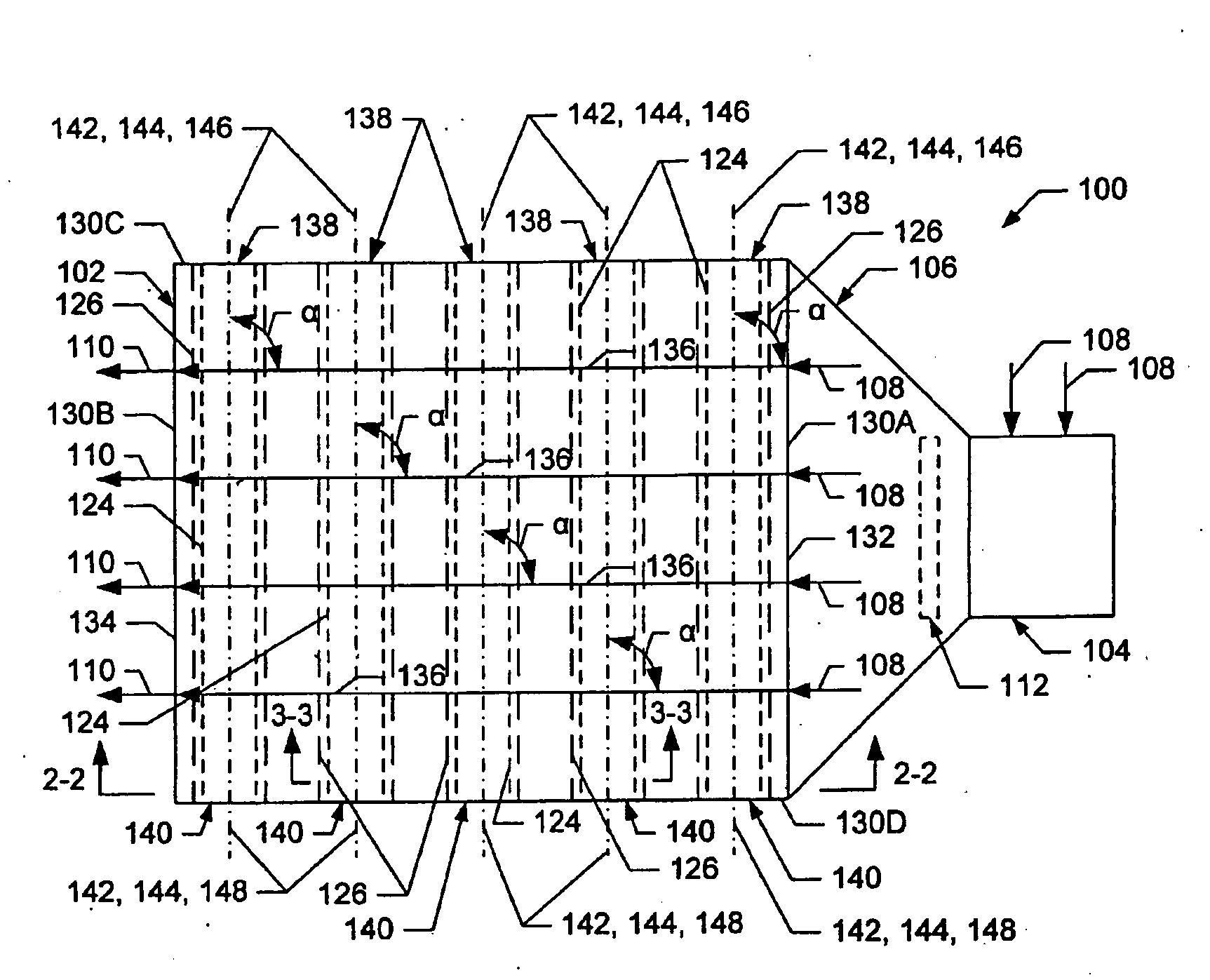
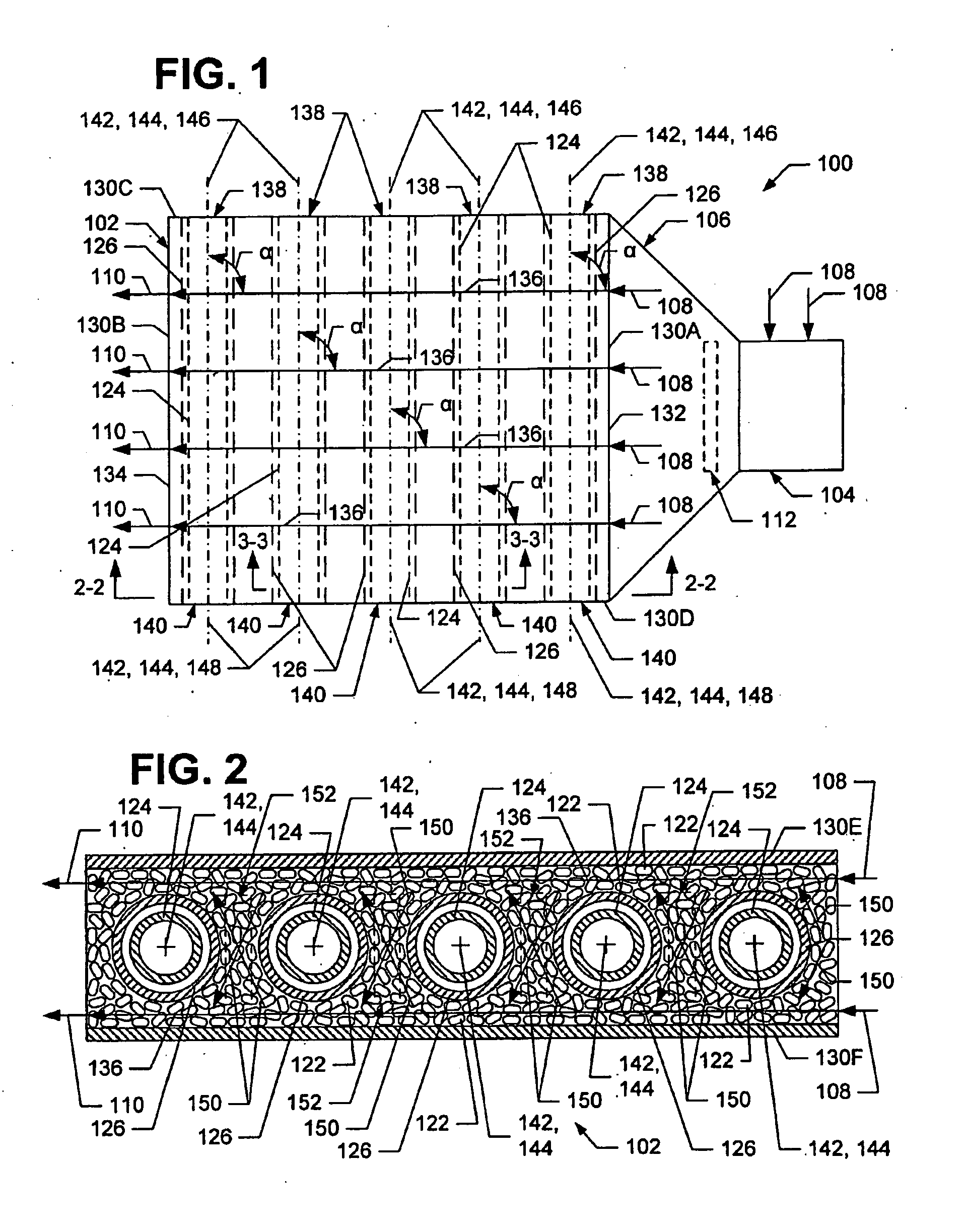
[0032]Referring now to the drawings in which like numerals represent like elements or steps throughout the several views, FIG. 1 is a schematic, top plan view of a photocatalytic air treatment system 100, according to a first embodiment of the present invention, for treating air by killing and / or mineralizing microorganisms and for oxidizing volatile organic compounds that may be present in the air. The photocatalytic air treatment system 100 comprises a reactor bed 102, an air-handling unit 104 and a transition member 106 interposed between and connected to the reactor bed 102 and the air-handling unit 104. The air-handling unit 104 is adapted to pull untreated air 108 (i.e., indicated by arrows 108) from the environment in which the photocatalytic air treatment system 100 is present or from another source and to direct the untreated air 108 into the reactor bed 102 via the transition member 106.

[0033]Generally, the air-handling unit 104 comprises a fan or blower that directs or bl...


PUM

PropertyMeasurementUnit
wavelengthaaaaaaaaaa
center-to-center distanceaaaaaaaaaa
distanceaaaaaaaaaa

Abstract

A photocatalytic air treatment system, including an apparatus and method, is provided for killing and/or mineralizing bacteria, viruses, mold, fungi, spores, mycotoxins, allergens, and other similar microorganisms and agents and similar organic matter, and for oxidizing volatile organic compounds. The system comprises one or more reactor beds configured in one or more stages with each reactor bed including a plurality of photocatalyst-coated media substantially surrounding a plurality of sheathed ultraviolet light sources. Adjacent ultraviolet light sources are positioned to create killing zones of photocatalyst coated media that are irradiated with ultraviolet light from the ultraviolet light sources and in which an increased number of hydroxyl radicals are present.

Description

CROSS REFERENCE TO RELATED APPLICATIONS[0001]This application is a continuation-in-part of, and claims the benefit of, U.S. patent application Ser. No. 11 / 728,949, filed Mar. 27, 2007; which in turn claims the benefit of U.S. Provisional Application Ser. No. 60 / 786,331, filed Mar. 27, 2006.FIELD OF THE INVENTION[0002]The present invention relates to air treatment systems. In a more specific aspect, this invention relates to air treatment systems and methods using a photocatalytic reaction (a) to kill and / or mineralize bacteria, viruses, mold, fungi, spores, mycotoxins, allergens and other similar microorganisms and agents and similar organic matter and (b) to oxidize volatile organic compounds.[0003]For purposes of this application, the term “microorganisms” will be used to collectively refer to such bacteria, viruses, mold, fungi, spores, mycotoxins, allergens and other similar microorganisms and agents.BACKGROUND OF THE INVENTION[0004]For many years, people have suffered adverse p...

Claims


Application Information

Patent Timeline
Patent Type & Authority Applications(United States)
IPC IPC(8): A61L9/20B01J19/12
CPCA61L9/205B01D53/007B01D53/885F25D2317/0417B01D2259/804F25D17/042B01D2255/802
Inventor HAYMAN, JR., JOHN J.
Owner AKIDA HLDG
Why Eureka
Try Eureka